
Homework Answers


Add Answer to:
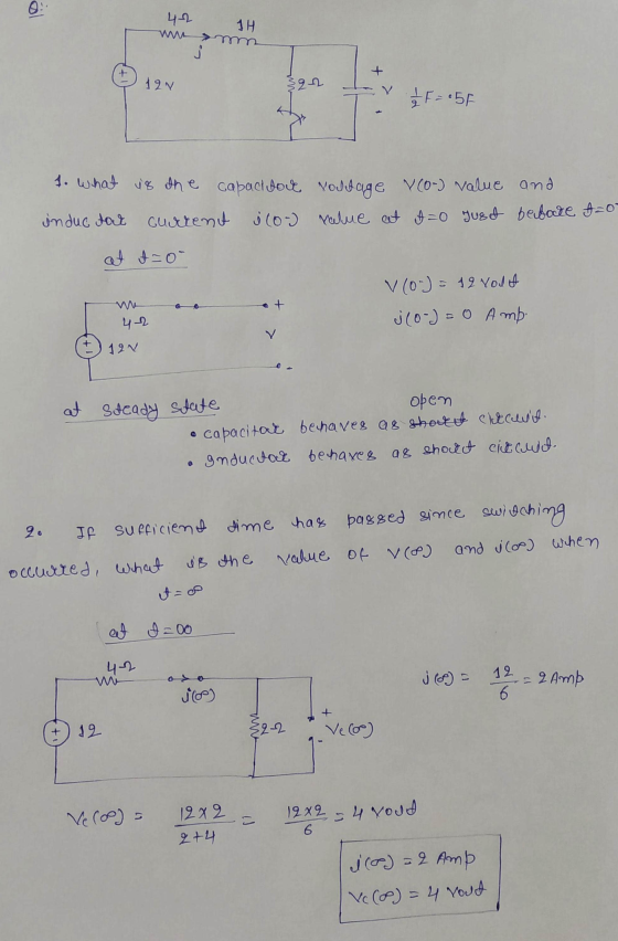
In the following circuit, the switch that had been OPEN for a
sufficient time was shorted...
The switch A in the circuit has been open for a long time. Calculate the voltage...
 The switch A in the circuit has been open for a long time.
Calculate the voltage u_2(t) after the switch is closed at t=0. The
capacitor C_1 has a initial voltage of u_1=100 V at t<0.
Capacitor C_2 lacks initial energy.
Rz = 200 kN2 R2 = 120 k12 + + C
The switch A in the circuit has been open for a long time.
Calculate the voltage u_2(t) after the switch is closed at t=0. The
capacitor C_1 has a initial voltage of u_1=100 V at t<0.
Capacitor C_2 lacks initial energy.
Rz = 200 kN2 R2 = 120 k12 + + C
AP 7.8 The switch in the circuit have been open for a long time. The initial...
 AP 7.8 The switch in the circuit have been open for a long time. The initial charge on the capacitor is 0. At t=0, switch is closed. Find the expression for i(t), v(t) for t> 0+. 0.1 µF X1%3D0% i(1) 7.5 mA( v(t) 20 k2 30 kn
For the circuit shown, the switch has been open for a long time and it closes...
 For the circuit shown, the switch has been open for a long time and it closes a t=0. The initial energy stored in capacitor is 250 . 102 w 3V 05v, 522 1c 20 F Question 6: What is the initial condition of the voltage of the capacitor? (A) 0 V (C) 1V (E) None of the above (B) 5 V (D) 3V (E) Question 7: What is the value of v, at t=0*? (A) -3V (C) 2V (E) None...
1. RLC Circuits Revisited. The first example of a RLC circuit illustrates the use of circuit...
 1. RLC Circuits Revisited. The first example of a RLC circuit illustrates the use of circuit elements in the s domain to represent initial conditions and a forced response. Next an example of sinusoidal excitation will follow where the transient response and steady state response are combined into one response waveform.. Transient RLC Circuit with Initial Conditions. Consider the RLC circuit below in Figure 7.14 which has two DC sources (Vco and V) applied before and after a switch is...
First-order circuits For the circuit shown below, the switch has been closed for a long time...
 First-order circuits For the circuit shown below, the switch has been closed for a long time and it is opened at t = 0. Calculate the capacitor voltage, v(t) for all t. 6.2 30V V 2F !
Consider the circuit depicted in Fig. 2. The switch SW1 has been closed for a long time before it...
 Consider the circuit depicted in Fig. 2. The switch SW1 has been closed for a long time before it is opened at time t = 0. The switch SW2 has been open for a long time before it is closed att = 0.1 (sec). i) Find the initial current I(0) flowing in the inductor and the initial voltage V(0) across the capacitor. ii) Find the voltage V(t) across the capacitor and the current I(t) through the inductor for 0 ≤ t ≤...
5. [RC Circuits] Consider the circuit shown in Figure 5 attached. As shown, the switch is...
 5. [RC Circuits] Consider the circuit shown in Figure 5 attached. As shown, the switch is in position "A" for t < 0, and the circuit has been at rest for a long time. At time t = 0, the switch opens and the capacitor starts to drain across the resistor. (a) When the switch is closed and there is only a direct current (DC) source, the capacitor acts like an open circuit. Find the constant voltage across the capacitor...
1. For the circuit below, the switch has been open for a long time and is...
 1. For the circuit below, the switch has been open for a long time and is then closed at t=0. a. Make an accurate sketch of the voltage on R3 versus time, labeling key values. (18 pts) b. Given that the time constant for this circuit is 80 ms, give the value of the voltage on R3 at t = 20 ms. (7 pts) Switch R 1 k 2 20 V R, 31 ΚΩ CE 100 UF R3 3 ΚΩ
1.(20 pts) The switch in the circuit shown below has been closed for a long time...
 1.(20 pts) The switch in the circuit shown below has been closed for a long time before it is opened at -0. (a) Is this RL or RC switching circuit. (b) Is this Natural or Step Response for t0? (c) Find veo'). (d) What is the time constant t of the circuit for t0? (e) Find Vco). (1) Write the expression for vct) fort >0. (g) Write the expression for ict) fort >0. (h) Write the expression for i(t) fort...
 The switch A in the circuit has been open for a long time.
Calculate the voltage u_2(t) after the switch is closed at t=0. The
capacitor C_1 has a initial voltage of u_1=100 V at t<0.
Capacitor C_2 lacks initial energy.
Rz = 200 kN2 R2 = 120 k12 + + C
The switch A in the circuit has been open for a long time.
Calculate the voltage u_2(t) after the switch is closed at t=0. The
capacitor C_1 has a initial voltage of u_1=100 V at t<0.
Capacitor C_2 lacks initial energy.
Rz = 200 kN2 R2 = 120 k12 + + C
 AP 7.8 The switch in the circuit have been open for a long time. The initial charge on the capacitor is 0. At t=0, switch is closed. Find the expression for i(t), v(t) for t> 0+. 0.1 µF X1%3D0% i(1) 7.5 mA( v(t) 20 k2 30 kn
 For the circuit shown, the switch has been open for a long time and it closes a t=0. The initial energy stored in capacitor is 250 . 102 w 3V 05v, 522 1c 20 F Question 6: What is the initial condition of the voltage of the capacitor? (A) 0 V (C) 1V (E) None of the above (B) 5 V (D) 3V (E) Question 7: What is the value of v, at t=0*? (A) -3V (C) 2V (E) None...
 1. RLC Circuits Revisited. The first example of a RLC circuit illustrates the use of circuit elements in the s domain to represent initial conditions and a forced response. Next an example of sinusoidal excitation will follow where the transient response and steady state response are combined into one response waveform.. Transient RLC Circuit with Initial Conditions. Consider the RLC circuit below in Figure 7.14 which has two DC sources (Vco and V) applied before and after a switch is...
 First-order circuits For the circuit shown below, the switch has been closed for a long time and it is opened at t = 0. Calculate the capacitor voltage, v(t) for all t. 6.2 30V V 2F !
 5. [RC Circuits] Consider the circuit shown in Figure 5 attached. As shown, the switch is in position "A" for t < 0, and the circuit has been at rest for a long time. At time t = 0, the switch opens and the capacitor starts to drain across the resistor. (a) When the switch is closed and there is only a direct current (DC) source, the capacitor acts like an open circuit. Find the constant voltage across the capacitor...
 1. For the circuit below, the switch has been open for a long time and is then closed at t=0. a. Make an accurate sketch of the voltage on R3 versus time, labeling key values. (18 pts) b. Given that the time constant for this circuit is 80 ms, give the value of the voltage on R3 at t = 20 ms. (7 pts) Switch R 1 k 2 20 V R, 31 ΚΩ CE 100 UF R3 3 ΚΩ
 1.(20 pts) The switch in the circuit shown below has been closed for a long time before it is opened at -0. (a) Is this RL or RC switching circuit. (b) Is this Natural or Step Response for t0? (c) Find veo'). (d) What is the time constant t of the circuit for t0? (e) Find Vco). (1) Write the expression for vct) fort >0. (g) Write the expression for ict) fort >0. (h) Write the expression for i(t) fort...
Most questions answered within 3 hours.
-
What mechanisms Drive speciation??
(I.e. what was Dawins theory on the orgin of species, and how...
asked 35 minutes ago -
The manager at a car assembly plant believes that the mean
assembly time for a car...
asked 1 hour ago -
Which of the following is true of electron capture?
A) It decreases the nuclide's mass number...
asked 3 hours ago -
Assuming an efficiency of 43.10%, calculate the actual yield of
magnesium nitrate formed from 114.9 g...
asked 3 hours ago -
The highly pathogenic bacterium Clostridium
perfringens causes gangrene, a disease that results in the
destruction of...
asked 5 hours ago -
In the context of situation analysis, which of the following is
a category for analysis in...
asked 5 hours ago -
In a study of the gas phase decomposition of sulfuryl chloride
at 600 K SO2Cl2(g)SO2(g) +...
asked 5 hours ago -
75 g of 2-propanol (C3H8O) and 25 g of pentane are mixed in a
200 mL...
asked 5 hours ago -
The 2800-turn coil in a dc motor has an area per turn of 1.1 ×
10-2...
asked 5 hours ago -
Draw a combinational logic circuit diagram with a symbol inside
the box for two I/P of...
asked 5 hours ago -
The cliché we use quite a lot in finance is: there is a need to
maximize...
asked 5 hours ago -
In class we discussed the addition of HCl to alpha pinene. Would
you expect one or...
asked 5 hours ago