
Homework Answers


Add Answer to:
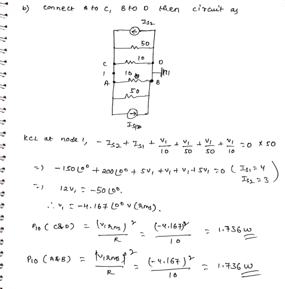
a) Find the average power delivered to each 10 ? resistor in the circuit shown in...
Calculate the power delivered to each resistor in the circuit shown in the figure below. (Let...
 Calculate the power delivered to each resistor in the circuit shown in the figure below. (Let R1-3.00 ?, R2-2.00 ?, and V-12.0 V.) resistor R 4.00-ohm resistor resistor R2 1.00-ohm resistor R2 1.00 ? 4.00 ?
Q2(a) Consider the circuit shown in Figure Q2a. Find the power delivered resistor. i. Calculate the...
 Q2(a) Consider the circuit shown in Figure Q2a. Find the power delivered resistor. i. Calculate the total resistance ii. Calculate the total current iii. Calculate the current in each branch iv. Calculate the voltage drop in each resistor v. Calculate the power delivered to each resistor. 2.012 20 V 1.022 3.0 22 w 4.0 52
Calculate the power delivered to each resistor in the circuit shown in the figure below. (Let...
 Calculate the power delivered to each resistor in the circuit shown in the figure below. (Let R1 - 3.000, R2 - 2.000, and V - 15.0 v.) resistor Ri w w 4.00-ohm resistor resistor R2 1.00-ohm resistor w w 1.00 w w 4.00 12 Need Help? Read it Watch
Problem 8 Part A Find the average power delivered to the 5 ks2 resistor in the...
 Problem 8 Part A Find the average power delivered to the 5 ks2 resistor in the circuit of (Figure 1). Suppose that Vr = 210 20° V (rms). Express your answer to three significant figures and include the appropriate units. View Available Hint(s) A th c ? P- Value Units Submit Figure 1 of 1> Provide Feedback 2002 25:10 50 35k Ideal Ideal
For the system shown in Figure 2: a) Find IS. b) Find the average power delivered...
 For the system shown in Figure 2: a) Find
IS. b) Find the average power delivered to each element. c) Find
the reactive power for each element. d) Find the apparent power for
each element. e) Find PT, QT, ST. f) Sketch the power triangle.
Figure 2 g) Find the power factor seen by the source E.
Problem 2 For the system shown in Figure 2: a) Find Is. R3 b) Find the average power delivered to each element c)...
For the system shown in Figure 2: a) Find
IS. b) Find the average power delivered to each element. c) Find
the reactive power for each element. d) Find the apparent power for
each element. e) Find PT, QT, ST. f) Sketch the power triangle.
Figure 2 g) Find the power factor seen by the source E.
Problem 2 For the system shown in Figure 2: a) Find Is. R3 b) Find the average power delivered to each element c)...
.) An unbalanced Y-Y circuit is shown in Figure 2. Find the average power delivered to...
 .) An unbalanced Y-Y circuit is shown in Figure 2. Find the average power delivered to the load. 21H 10 cos (4t - 90°) 20 2H 10 cos 4150°) 4Ω 2H 10 cos (4t + 30°) Source Line Load Figure 2
Given the circuit and find the average Power absorbed by the 10 Ohm resistor. Question 4...
 Given the circuit and find the average Power absorbed
by the 10 Ohm resistor.
Question 4 [20] Given the circuit of Fig. 3.4 find the average power absorbed by the 100 resistor -50 40 8V 220° ontv 0.1VO 81 50 Fig. 3.4 Question 5 65 lagging power factor and an efficiency
Given the circuit and find the average Power absorbed
by the 10 Ohm resistor.
Question 4 [20] Given the circuit of Fig. 3.4 find the average power absorbed by the 100 resistor -50 40 8V 220° ontv 0.1VO 81 50 Fig. 3.4 Question 5 65 lagging power factor and an efficiency
Find the Thevenin Equivalent circuit for the circuit shown below as seen by the load resistor...
 Find the Thevenin Equivalent circuit for the circuit shown below as seen by the load resistor RL connected across terminals A and B. What is the maximum power can be absorbed by RL? [Sp2014 Exam 1] 5012 125V
Calculate the power delivered to each resistor in the circult shown in the figure below. (Let...
 Calculate the power delivered to each resistor in the circult shown in the figure below. (Let R - 5.00 0, R2 = 2.000, and V - 21.0 V.) R} 1.000 w 4.00 2 resistor R, 4.00-ohm resistor resistor R 1.00-ohm resistor Need Help? Read Watch
7.2Ω 6Ω 2) For the circuit shown, find (a) the voltage Vo; (b) the power delivered...
 7.2Ω 6Ω 2) For the circuit shown, find (a) the voltage Vo; (b) the power delivered to the circuit by the current source; and (c) the power dissipated in the 10Ω resistor. Vo 300 64Ω 10Ω
 Calculate the power delivered to each resistor in the circuit shown in the figure below. (Let R1-3.00 ?, R2-2.00 ?, and V-12.0 V.) resistor R 4.00-ohm resistor resistor R2 1.00-ohm resistor R2 1.00 ? 4.00 ?
 Q2(a) Consider the circuit shown in Figure Q2a. Find the power delivered resistor. i. Calculate the total resistance ii. Calculate the total current iii. Calculate the current in each branch iv. Calculate the voltage drop in each resistor v. Calculate the power delivered to each resistor. 2.012 20 V 1.022 3.0 22 w 4.0 52
 Calculate the power delivered to each resistor in the circuit shown in the figure below. (Let R1 - 3.000, R2 - 2.000, and V - 15.0 v.) resistor Ri w w 4.00-ohm resistor resistor R2 1.00-ohm resistor w w 1.00 w w 4.00 12 Need Help? Read it Watch
 Problem 8 Part A Find the average power delivered to the 5 ks2 resistor in the circuit of (Figure 1). Suppose that Vr = 210 20° V (rms). Express your answer to three significant figures and include the appropriate units. View Available Hint(s) A th c ? P- Value Units Submit Figure 1 of 1> Provide Feedback 2002 25:10 50 35k Ideal Ideal
 For the system shown in Figure 2: a) Find
IS. b) Find the average power delivered to each element. c) Find
the reactive power for each element. d) Find the apparent power for
each element. e) Find PT, QT, ST. f) Sketch the power triangle.
Figure 2 g) Find the power factor seen by the source E.
Problem 2 For the system shown in Figure 2: a) Find Is. R3 b) Find the average power delivered to each element c)...
For the system shown in Figure 2: a) Find
IS. b) Find the average power delivered to each element. c) Find
the reactive power for each element. d) Find the apparent power for
each element. e) Find PT, QT, ST. f) Sketch the power triangle.
Figure 2 g) Find the power factor seen by the source E.
Problem 2 For the system shown in Figure 2: a) Find Is. R3 b) Find the average power delivered to each element c)...
 .) An unbalanced Y-Y circuit is shown in Figure 2. Find the average power delivered to the load. 21H 10 cos (4t - 90°) 20 2H 10 cos 4150°) 4Ω 2H 10 cos (4t + 30°) Source Line Load Figure 2
 Given the circuit and find the average Power absorbed
by the 10 Ohm resistor.
Question 4 [20] Given the circuit of Fig. 3.4 find the average power absorbed by the 100 resistor -50 40 8V 220° ontv 0.1VO 81 50 Fig. 3.4 Question 5 65 lagging power factor and an efficiency
Given the circuit and find the average Power absorbed
by the 10 Ohm resistor.
Question 4 [20] Given the circuit of Fig. 3.4 find the average power absorbed by the 100 resistor -50 40 8V 220° ontv 0.1VO 81 50 Fig. 3.4 Question 5 65 lagging power factor and an efficiency
 Find the Thevenin Equivalent circuit for the circuit shown below as seen by the load resistor RL connected across terminals A and B. What is the maximum power can be absorbed by RL? [Sp2014 Exam 1] 5012 125V
 Calculate the power delivered to each resistor in the circult shown in the figure below. (Let R - 5.00 0, R2 = 2.000, and V - 21.0 V.) R} 1.000 w 4.00 2 resistor R, 4.00-ohm resistor resistor R 1.00-ohm resistor Need Help? Read Watch
 7.2Ω 6Ω 2) For the circuit shown, find (a) the voltage Vo; (b) the power delivered to the circuit by the current source; and (c) the power dissipated in the 10Ω resistor. Vo 300 64Ω 10Ω
Most questions answered within 3 hours.
-
What specific indicators can point to lack of progress for
African Americans in American society?
asked 46 minutes ago -
1-The Electrons in a beam are moving at 2.7×10⁸ m/s in an
electric field of 15000...
asked 1 hour ago -
A gas tank is a vertical cylinder. It has a radius of 1m, a
height of...
asked 1 hour ago -
Accent Software faces the following conditions. All of these
support Accent’s use of a market-penetration pricing...
asked 2 hours ago -
A mathematically inclined friend emails you the following
instructions: "Meet me in the cafeteria the first...
asked 2 hours ago -
A monopoly sells in two countries . The demand curves in the two
countries are p1...
asked 3 hours ago -
A .15kg rubber ball is bounced off a wall. Before hitting the
wall, the ball moves...
asked 4 hours ago -
A manufacturing company preparing to build a new plant is
considering three potential locations for it....
asked 4 hours ago -
B. If compound Y has approximately the same values of solubility
in toluene as compound X,...
asked 4 hours ago -
Oscar Inc. has inventory in Japan valued at 39,051,000 Yen one
year ago. One year ago...
asked 5 hours ago -
If Canada suffered from "fundamental disequilibrium," and its
government choose not to devalue its currency, a...
asked 5 hours ago -
4. How many input & output Key Value Pairs are passed into,
and emitted out of...
asked 5 hours ago