
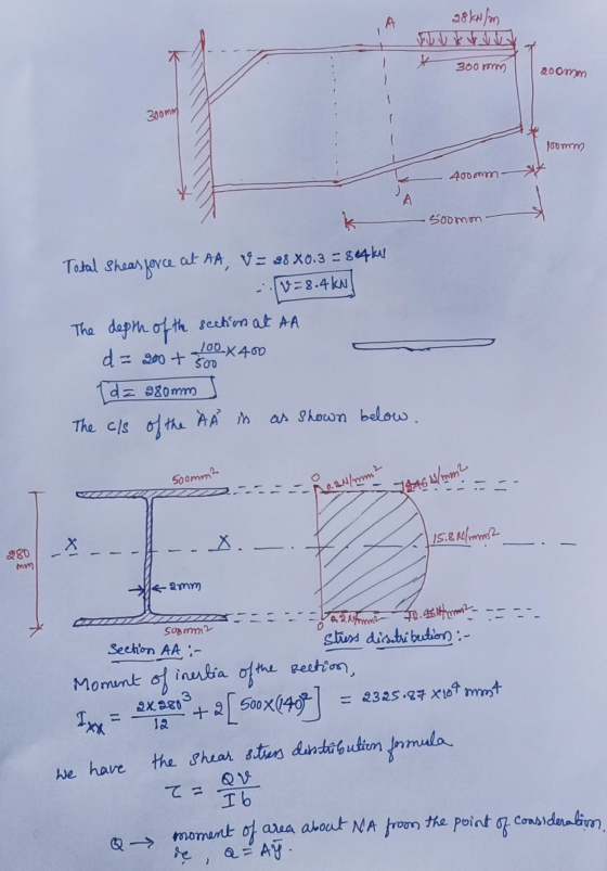
28 (kN / m) distributed load on the flange and web formed in the
figure
It is applied. The cross-sectional area of each flange is 500
mm2
'Dr. The beam of the beam is 2 mm thick
it carries normal stress. Calculate the shear flux distribution on
the screen in AA section
Draw. Show all the calculation steps step by step in detail.
Homework Answers

Add Answer to:
28 (kN / m) distributed load on the flange and web formed in the
figure
It...
FLANGE. 44" THICK Problem 6. THIS IS A STEEL WIDE FLANGE SECTION W 16 X 31....
 FLANGE. 44" THICK Problem 6. THIS IS A STEEL WIDE FLANGE SECTION W 16 X 31. THIS BEAM SPANS 20 FEET AND CARRIES A LOAD OF 3 KIPS PER FOOT ALONG ITS LENGTH. CALCULATE THE MAXIMUM BENDING STRESS AND THE MAXIMUM SHEAR STRESS GENERATED IN THIS BEAM. E NEUTRAL AXIS WEB 275" THICK
Learning Goal: To calculate the shear stress at the web/flange joint in a beam and use...
 Learning Goal: To calculate the shear stress at the web/flange joint in a beam and use that stress to calculate the required nail spacing to make a built- up beam. A built up beam can be constructed by fastening flat plates together. When an l-beam is subjected to a shear load, internal shear stress is developed at every cross section, with longitudinal shear stress balancing transverse shear stress. If the beam is built up using plates, the fasteners used must...
A5.2 m long simply supported wood beam carries a uniformly distributed load of 12.9 kN/m, as...
 A5.2 m long simply supported wood beam carries a uniformly distributed load of 12.9 kN/m, as shown in Figure A. The cross-sectional dimensions of the beam as shown in Figure Bare b = 195 mm, d = 485 mm. yy = 81 mm, and yx = 167 mm. Section 3-a is located at x = 1.4 m from B. (a) At section a-a, determine the magnitude of the shear stress in the beam at point H. (b) At section a-3,...
Q1 A cantilever beam carries a horizontal point load P of 100 kN at its end,...
 Q1 A cantilever beam carries a horizontal point load P of 100 kN at its end, as shown in Figure Q1 (a). In this case, the self weight of the beam must be included. The beam is made from a square box section with a width of b and a depth of b (refer to Figure Q1 (b)). The density of the beam is 20 kN/m² and the maximum allowable longitudinal stress of the beam is 200 N/mm2.K b P=...
shearing stress in beams(I section)
An I-section girder 12 cm deep has the following cross-sectional dimensions: Top flange 6 cm wide by 1 cm thick, bottom flange 12 cm wide by 1 cm thick, web 1 cm thick, web 1 cm thick. The girder is 5 m long simply supported over a span of 3 m, overhanging both supports by the same amount and it carries a concentrated load of 2 kN each end. Find the maximum stress in the material due to bending.
Q1 A simply supported beam of length L = 10 m carries a uniformly distributed load...
 Q1 A simply supported beam of length L = 10 m carries a uniformly distributed load w = of 10 kN/m, as shown in Figure Q1 (a). The beam is made from a I-section and the thickness for all the three rectangular members is of 10 mm. All other dimensions are illustrated in Figure Q1 (b). Self-weight of the beam is neglected. 300 mm w = 10 kN/m 300 mm L/4 L/2 L/4 300 mm Figure Q1 (a) Figure Q1...
Q2 A simply supported beam of length L = 10 m carries a uniformly distributed load...
 Q2 A simply supported beam of length L = 10 m carries a uniformly distributed load w = of 10 kN/m, as shown in Figure Q2 (a). The beam is made from a I-section and the thickness for all the three rectangular members is of 10 mm. All other dimensions are illustrated in Figure Q2 (b). Self-weight of the beam is neglected. 300 mm w = 10 kN/m т 300 mm 已 L/44 L/2 L/44 300 mm Figure Q2 (a)...
Q2 A simply supported beam of length L = 10 m carries a uniformly distributed load...
 Q2 A simply supported beam of length L = 10 m carries a uniformly distributed load w of 10 kN/m, as shown in Figure Q2 (a). The beam is made from a symmetrical I-section and consists of three equal rectangular members of 100 mm x 10 mm (see Figure Q2 (b)). Self- weight of the beam is neglected. 100 mm w = 10 kN/m A- - A 100 mm 77777 L/3 L/3 L/3 — Figure Q2 (a) Figure Q2 (b)...
(a) If the wide-flange beam shown in Figure Q4a is subjected to a shear of V = 23 kN
 (a) If the wide-flange beam shown in Figure Q4a is subjected to a shear of V = 23 kN i. Calculate the moment of inertia of the cross section about the neutral axis.ii. Determine the shear stress on the web at A.(b) The state of stress at a point is shown on the element in Figure Q4b. Determine graphically using Mohr's circle i. The principal stresses. ii. The orientation of the principal planes.iii. The maximum in-plane shear stress and average normal stress at...
QI A simply supported beam of length L = 10 m carries a uniformly distributed load...
 QI A simply supported beam of length L = 10 m carries a uniformly distributed load w of 10 kN/m, as shown in Figure QI (a). The beam is made from a symmetrical I-section and consists of three equal rectangular members of 100 mm x 10 mm (see Figure QI (b)). Self- weight of the beam is neglected. 100 mm w = 10 kN/m A-1 A 100 mm 1/3 L/3 L/3 m [5] Figure Q1 (a) Figure Q1 (b) (a)...
 FLANGE. 44" THICK Problem 6. THIS IS A STEEL WIDE FLANGE SECTION W 16 X 31. THIS BEAM SPANS 20 FEET AND CARRIES A LOAD OF 3 KIPS PER FOOT ALONG ITS LENGTH. CALCULATE THE MAXIMUM BENDING STRESS AND THE MAXIMUM SHEAR STRESS GENERATED IN THIS BEAM. E NEUTRAL AXIS WEB 275" THICK
 Learning Goal: To calculate the shear stress at the web/flange joint in a beam and use that stress to calculate the required nail spacing to make a built- up beam. A built up beam can be constructed by fastening flat plates together. When an l-beam is subjected to a shear load, internal shear stress is developed at every cross section, with longitudinal shear stress balancing transverse shear stress. If the beam is built up using plates, the fasteners used must...
 A5.2 m long simply supported wood beam carries a uniformly distributed load of 12.9 kN/m, as shown in Figure A. The cross-sectional dimensions of the beam as shown in Figure Bare b = 195 mm, d = 485 mm. yy = 81 mm, and yx = 167 mm. Section 3-a is located at x = 1.4 m from B. (a) At section a-a, determine the magnitude of the shear stress in the beam at point H. (b) At section a-3,...
 Q1 A cantilever beam carries a horizontal point load P of 100 kN at its end, as shown in Figure Q1 (a). In this case, the self weight of the beam must be included. The beam is made from a square box section with a width of b and a depth of b (refer to Figure Q1 (b)). The density of the beam is 20 kN/m² and the maximum allowable longitudinal stress of the beam is 200 N/mm2.K b P=...
 Q1 A simply supported beam of length L = 10 m carries a uniformly distributed load w = of 10 kN/m, as shown in Figure Q1 (a). The beam is made from a I-section and the thickness for all the three rectangular members is of 10 mm. All other dimensions are illustrated in Figure Q1 (b). Self-weight of the beam is neglected. 300 mm w = 10 kN/m 300 mm L/4 L/2 L/4 300 mm Figure Q1 (a) Figure Q1...
 Q2 A simply supported beam of length L = 10 m carries a uniformly distributed load w = of 10 kN/m, as shown in Figure Q2 (a). The beam is made from a I-section and the thickness for all the three rectangular members is of 10 mm. All other dimensions are illustrated in Figure Q2 (b). Self-weight of the beam is neglected. 300 mm w = 10 kN/m т 300 mm 已 L/44 L/2 L/44 300 mm Figure Q2 (a)...
 Q2 A simply supported beam of length L = 10 m carries a uniformly distributed load w of 10 kN/m, as shown in Figure Q2 (a). The beam is made from a symmetrical I-section and consists of three equal rectangular members of 100 mm x 10 mm (see Figure Q2 (b)). Self- weight of the beam is neglected. 100 mm w = 10 kN/m A- - A 100 mm 77777 L/3 L/3 L/3 — Figure Q2 (a) Figure Q2 (b)...
 QI A simply supported beam of length L = 10 m carries a uniformly distributed load w of 10 kN/m, as shown in Figure QI (a). The beam is made from a symmetrical I-section and consists of three equal rectangular members of 100 mm x 10 mm (see Figure QI (b)). Self- weight of the beam is neglected. 100 mm w = 10 kN/m A-1 A 100 mm 1/3 L/3 L/3 m [5] Figure Q1 (a) Figure Q1 (b) (a)...
Most questions answered within 3 hours.
-
1-The Electrons in a beam are moving at 2.7×10⁸ m/s in an
electric field of 15000...
asked 3 minutes ago -
A gas tank is a vertical cylinder. It has a radius of 1m, a
height of...
asked 30 minutes ago -
Accent Software faces the following conditions. All of these
support Accent’s use of a market-penetration pricing...
asked 1 hour ago -
A mathematically inclined friend emails you the following
instructions: "Meet me in the cafeteria the first...
asked 1 hour ago -
A monopoly sells in two countries . The demand curves in the two
countries are p1...
asked 2 hours ago -
A .15kg rubber ball is bounced off a wall. Before hitting the
wall, the ball moves...
asked 3 hours ago -
A manufacturing company preparing to build a new plant is
considering three potential locations for it....
asked 3 hours ago -
B. If compound Y has approximately the same values of solubility
in toluene as compound X,...
asked 3 hours ago -
Oscar Inc. has inventory in Japan valued at 39,051,000 Yen one
year ago. One year ago...
asked 4 hours ago -
If Canada suffered from "fundamental disequilibrium," and its
government choose not to devalue its currency, a...
asked 4 hours ago -
4. How many input & output Key Value Pairs are passed into,
and emitted out of...
asked 4 hours ago -
Why would your heart not function well if constructed of
skeletal muscle? What is the particular...
asked 4 hours ago