To understand the units of inductance, the potential energy stored in an inductor, and some of the consequences of having inductance in a circuit.
After batteries, resistors, and capacitors, the most common elements in circuits are inductors. Inductors usually look like tightly wound coils of fine wire. Unlike capacitors, which produce a physical break in the circuit between the capacitor plates, the wire of an inductor provides an unbroken continuous path in which current can flow. When the current in a circuit is constant, an inductor acts essentially like a short circuit (i.e., a zero-resistance path). In reality, there is always at least a small amount of resistance in the windings of an inductor, a fact that is usually neglected in introductory discussions.
Recall that current flowing through a wire generates a magnetic field in the vicinity of the wire. If the wire is coiled , such as in a solenoid or an inductor, the magnetic field is strongest within the coil parallel to its axis. The magnetic field associated with current flowing through an inductor takes time to create, and time to eliminate when the current is turned off. When the current changes, an EMF is generated in the inductor, according to Faraday's law, that opposes the change in current flow. Thus inductors provide electrical inertia to a circuit by reducing the rapidity of change in the current flow.


Homework Answers
PART A
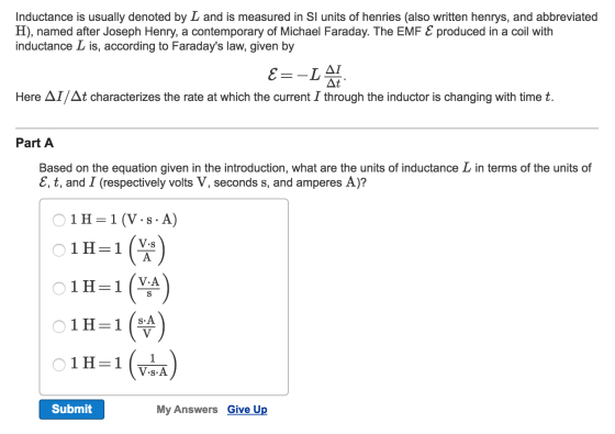
It is given
ε = -LΔI/Δt
-εΔt/ΔI = L
Hence the unit is Vs/A
1H = 1(V.s/A)
PART B
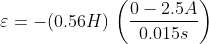
The inductance of the waffle iron L = 560 x 10-3 H = 0.56 H
Initial current flowing in circuit I = 2.5 A
Tame taken for current to become zero Δt = 0.015 s
ε = -LΔI/Δt
ε = - 0.56 x (0 - 2.5)/0.015
ε = 93.33 V
PART C
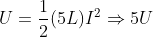
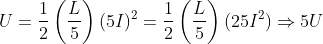
- Increasing the inductance by a factor of 5; leaving the current unchanged
- Leaving the inductance unchanged; increasing the current by a factor of √5
- Reducing the inductance by a factor of 5; increasing the current by a factor of 5
PART D
As per the given information, the curve of Current Vs time must be continuous and the slope must not be infinite
Hence the curves A, B and C are possible graphs
Answer is ABC
part A
since,

by re-arranging, we can write

now, unit of inductor is Henry, unit of time is second and unit of current and emf is A and V, therefore

Part -B
Given that,
The inductance of the waffle iron is,


and Initial current flowing in circuit is ,

and time taken by current to become zero is,

therefore,

part C
1. Increasing the inductance by a factor of 5; leaving the current unchanged
2. Leaving the inductance unchanged; increasing the current by a factor of √5

3. Reducing the inductance by a factor of 5; increasing the current by a factor of 5,
Part d
As per the given information, the curve of Current Vs time must be continuous and the slope must not be infinite
Hence the curves A, B and C are possible graphs
Answer is ABC
Add Answer to:
To understand the units of inductance, the potential energy
stored in an inductor, and some of...
a.) An inductor carries a current of 4.4 A, and the magnetic energy stored in the...
a.) An inductor carries a current of 4.4 A, and the magnetic energy stored in the inductor is 0.0022 J. What is the inductance? mH b.) An inductor with L = 1.4 mH is connected to a circuit that produces a current increasing steadily from 1.8 A to 5.2 A over a time of 2.6 s. What is the voltage across the inductor? mV
An LR circuit includes a resistor of resistance R, an inductor of inductance L and a...
An LR circuit includes a resistor of resistance R, an inductor of inductance L and a battery of emf E = 10 V. At time t = 0 the current in the circuit is I = 0. At time t = 6.1 ms the current is I = 0.66 A. Assume R = 100ohms, find L.
0/1 pts Et Question 2 Two inductors are placed in a circuit in series with each other. Inductor 1 has an inductance of...
 0/1 pts Et Question 2 Two inductors are placed in a circuit in series with each other. Inductor 1 has an inductance of 3.5e-3 H and inductor 2 has an inductance of 8.9e-2 H. Anytime current is running through the inductors, what is the ratio of energy stored in inductor 1 compared to inductor 2? U1 is the energy in inductor 1 and U2 is the energy in inductor 2 U1-3.93e-2 U2 U1 744.68 U2 U1-1.55e-3 U2 U1-25.36 U2
An inductor is an electrical device that can store energy in the form of a magnetic...
 An inductor is an electrical device that can store energy in the form of a magnetic field. Click the icon to view the information about inductors and inductance. Click the icon to view the relationship between Cross-sectional area and Inductance. (a) What are the units of the slope (9.66)? A More Info A More Info The units of the slope are - In the simplest form, an inductor is a cylindrical coil of wire, and its inductance (L), measured in...
1. An RL circuit comprised of one resistor and one inductor is shown in the figure below. The resistor and inductor...
 1. An RL circuit comprised of one resistor and one inductor is shown in the figure below. The resistor and inductor are connected to a source of emf with negligible internal resistance by a switch a. The emf for this circuit is 12.0 V. The resistance of the resistor is 0.35 , and the inductance of the inductor is 53 mH. For the circuit below: a. Sketch the graph of current through the inductor as a function of time after...
A circuit is constructed with two capacitors and an inductor as shown. The values for the...
 A circuit is constructed with two capacitors and an inductor as shown. The values for the capacitors are: C1-541 uF and C2-126 uF. The inductance is L-332 mH. At time t -0, the current through the inductor has its maximum value IL(0)-176 mA and it has the direction shown a 1) What is ?0, the resonant frequency of this circuit? radians/s Submit 2) What is Q1(t1), the charge on the capacitor C1 at time t t 21.3 ms? The sign...
1. An RL circuit comprised of one resistor and one inductor is shown in the figure...
 1. An RL circuit comprised of one resistor and one inductor is shown in the figure below. The resistor and inductor are connected to a source of emf with negligible internal resistance by a switch a. The emf for this circuit is 12.0 V. The resistance of the resistor is 0.35 12, and the inductance of the inductor is 53 mH. For the circuit below: a. Sketch the graph of current through the inductor as a function of time after...
Please show steps and answer. A circuit is constructed with two capacitors and an inductor as...
 Please show steps and answer.
A circuit is constructed with two capacitors and an inductor as shown. The values for the capacitors are: C1 = 324 muF and C2 = 364 muF. The inductance is L = 212 mH. At time t =0, the current through the inductor has its maximum value IL(0) = 135 mA and it has the direction shown. 1) What is wo, the resonant frequency of this circuit? radians/s 2) What is Q1(t1), the charge on...
Please show steps and answer.
A circuit is constructed with two capacitors and an inductor as shown. The values for the capacitors are: C1 = 324 muF and C2 = 364 muF. The inductance is L = 212 mH. At time t =0, the current through the inductor has its maximum value IL(0) = 135 mA and it has the direction shown. 1) What is wo, the resonant frequency of this circuit? radians/s 2) What is Q1(t1), the charge on...
One or two sentence answers are fine. But please be clear with explanations. For each statement,...
One or two sentence answers are fine. But please be clear with explanations. For each statement, decide whether it is always true, always false or true in certain circumstances. State which case applies to the statement, describing why you chose the answer you did and cite an experiment or principle of Physics which supports` your claim. [1] In a capacitor in an AC circuit, the electric field leads the current. [2] The impedance of a capacitor increases with frequency. [3]...
 0/1 pts Et Question 2 Two inductors are placed in a circuit in series with each other. Inductor 1 has an inductance of 3.5e-3 H and inductor 2 has an inductance of 8.9e-2 H. Anytime current is running through the inductors, what is the ratio of energy stored in inductor 1 compared to inductor 2? U1 is the energy in inductor 1 and U2 is the energy in inductor 2 U1-3.93e-2 U2 U1 744.68 U2 U1-1.55e-3 U2 U1-25.36 U2
 An inductor is an electrical device that can store energy in the form of a magnetic field. Click the icon to view the information about inductors and inductance. Click the icon to view the relationship between Cross-sectional area and Inductance. (a) What are the units of the slope (9.66)? A More Info A More Info The units of the slope are - In the simplest form, an inductor is a cylindrical coil of wire, and its inductance (L), measured in...
 1. An RL circuit comprised of one resistor and one inductor is shown in the figure below. The resistor and inductor are connected to a source of emf with negligible internal resistance by a switch a. The emf for this circuit is 12.0 V. The resistance of the resistor is 0.35 , and the inductance of the inductor is 53 mH. For the circuit below: a. Sketch the graph of current through the inductor as a function of time after...
 A circuit is constructed with two capacitors and an inductor as shown. The values for the capacitors are: C1-541 uF and C2-126 uF. The inductance is L-332 mH. At time t -0, the current through the inductor has its maximum value IL(0)-176 mA and it has the direction shown a 1) What is ?0, the resonant frequency of this circuit? radians/s Submit 2) What is Q1(t1), the charge on the capacitor C1 at time t t 21.3 ms? The sign...
 1. An RL circuit comprised of one resistor and one inductor is shown in the figure below. The resistor and inductor are connected to a source of emf with negligible internal resistance by a switch a. The emf for this circuit is 12.0 V. The resistance of the resistor is 0.35 12, and the inductance of the inductor is 53 mH. For the circuit below: a. Sketch the graph of current through the inductor as a function of time after...
 1. An RL circuit comprised of one resistor and one inductor is shown in the figure below. The resistor and inductor are connected to a source of emf with negligible internal resistance by a switch a. The emf for this circuit is 12.0 V. The resistance of the resistor is 0.35 12, and the inductance of the inductor is 53 mH. For the circuit below: a. Sketch the graph of current through the inductor as a function of time after...
 Please show steps and answer.
A circuit is constructed with two capacitors and an inductor as shown. The values for the capacitors are: C1 = 324 muF and C2 = 364 muF. The inductance is L = 212 mH. At time t =0, the current through the inductor has its maximum value IL(0) = 135 mA and it has the direction shown. 1) What is wo, the resonant frequency of this circuit? radians/s 2) What is Q1(t1), the charge on...
Please show steps and answer.
A circuit is constructed with two capacitors and an inductor as shown. The values for the capacitors are: C1 = 324 muF and C2 = 364 muF. The inductance is L = 212 mH. At time t =0, the current through the inductor has its maximum value IL(0) = 135 mA and it has the direction shown. 1) What is wo, the resonant frequency of this circuit? radians/s 2) What is Q1(t1), the charge on...
Most questions answered within 3 hours.
-
1) If Nominal GDP is $16,000 billion and the GDP deflator is 50,
then Real GDP...
asked 1 minute ago -
D. A student completed 20 courses in the School of Arts and
Sciences. Her grades in...
asked 1 hour ago -
teo
pucks moving on a frictionless air table are about to collide. the
1.5 kg puck...
asked 1 hour ago -
Problem #1
The area between Z = 0 and Z = 2.50
The area between Z...
asked 3 hours ago -
1. What is the meaning of the term communication style?
2. What are the benefits to...
asked 2 hours ago -
9.) You are buying a car that cost $26,500. You make payments of
$412 each month...
asked 3 hours ago -
. Suppose a discrete random variable has probability
distribution
P(x) = .2 if x = 0...
asked 4 hours ago -
Under the influence of its drive force, a snowmobile is moving
at a constant velocity along...
asked 4 hours ago -
Why do organizations decline? What steps can top
management take to halt, decline, and restore organizational...
asked 4 hours ago -
What mechanisms Drive speciation??
(I.e. what was Dawins theory on the orgin of species, and how...
asked 6 hours ago -
The manager at a car assembly plant believes that the mean
assembly time for a car...
asked 7 hours ago -
Which of the following is true of electron capture?
A) It decreases the nuclide's mass number...
asked 8 hours ago