

Homework Answers

Add Answer to:
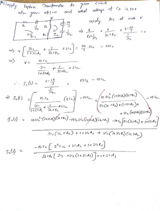
Problem 3. Using the Laplace transformation, obtain the current I2(s) of Problem 1. Assume that all...
Problem 3 Using the Laplace transform, find the Laplace currents and real time currents in the...
 Problem 3 Using the Laplace transform, find the Laplace currents and real time currents in the resistor and inductor. Assume the inductor current is zero at t=0. ਕਾ 25 te-75t u(t) ( ਅਤੁਟਕਾ ... RS200 2 4 H
Only need the last question 5 thanks! 3) RLC Parallel Circuits: Differential Equations and Laplace U2...
 Only need the last question 5 thanks!
3) RLC Parallel Circuits: Differential Equations and Laplace U2 U1 TOPEN 0 TCLOSE 0 L1 R1 0.15H C1 2E-8F 11 10E-3 2 10E-3 At t 0, U1 closes and U2 opens. 3.1: What is the intial (t-0+) current through the capacitor? What is the initial (t=0+) voltage across the capacitor? 3.2: What is the DC steady state current though the capacitor ast goes to infinity? 3.3: Find the current through the CAPACITOR as...
Only need the last question 5 thanks!
3) RLC Parallel Circuits: Differential Equations and Laplace U2 U1 TOPEN 0 TCLOSE 0 L1 R1 0.15H C1 2E-8F 11 10E-3 2 10E-3 At t 0, U1 closes and U2 opens. 3.1: What is the intial (t-0+) current through the capacitor? What is the initial (t=0+) voltage across the capacitor? 3.2: What is the DC steady state current though the capacitor ast goes to infinity? 3.3: Find the current through the CAPACITOR as...
3) RLC Parallel Circu its: Differential Equations and Laplace U2 U1 TOPEN 0 TCLOSE 0 CL1 R1 0.15H C1 2E-8F 1 10E-3 2 J...
 3) RLC Parallel Circu its: Differential Equations and Laplace U2 U1 TOPEN 0 TCLOSE 0 CL1 R1 0.15H C1 2E-8F 1 10E-3 2 J 10E-3 Att-0, U1 closes and U2 opens. 3.1: What is the intial (t-0+) current through the capacitor? What is the inital (t-0+) voltage across the capacitor? 3.2: What is the DC steady state current though the capacitor as t goes to infinity? 3.3: Find the current through the CAPACITOR as a function of time for R...
1. Study the sample problem sheet for problem 3-1. Use the circuit of Figure P3- 1...
 1. Study the sample problem sheet for problem 3-1. Use the circuit of Figure P3- 1 with el(t) 5u(t)-5u(t-2) and e2(t) 8tu(t) and solve for the two currents il(t) and i2(t) 40 ena) e과。 くー410) (-2の Figure P3-1 2. Use the circuit of Figure P3-1 with el(t)- 4sin wt and e2(t) 5cos ut the two currents i1(t) and i2(t). Express each current as a single sinusoid. and solve for 3. Determine the Thevenin equivalent for Figure P3-8 with i(t) 4u(t...
1- Find the currents Ii and I2 and the voltage VAB 2Ω 6 V 2- Initially...
 1- Find the currents Ii and I2 and the voltage VAB 2Ω 6 V 2- Initially the capacitor is charged with 20 uC. At t-0 the switch is closed. Find the time constant, the initial current in the circuit (at t-0), and the time needed for the current to drop to 1/3 of its initial value. Veキ104F
Problem 1: Find the Laplace transform X(s) of x(0)-6cos(Sr-3)u(t-3). 10 Problem 2: (a) Find the inverse...
 Problem 1: Find the Laplace transform X(s) of x(0)-6cos(Sr-3)u(t-3). 10 Problem 2: (a) Find the inverse Laplace transform h() of H(s)-10s+34 (Hint: use the Laplace transform pair for Decaying Sine or Generic Oscillatory Decay.) (b) Draw the corresponding direct form II block diagram of the system described by H(s) and (c) determine the corresponding differential equation. Problem 3: Using the unilateral Laplace transform, solve the following differential equation with the given initial condition: y)+5y(0) 2u), y(0)1 Problem 4: For the...
Circuit Analysis in the s-Domain 15.3. The initial voltage across the capacitor in the circuit shown in Figure P15.3 is v(0) 1 V, and the initial current through the inductor is i(0)0 mA Find th...
 Circuit Analysis in the s-Domain 15.3. The initial voltage across the capacitor in the circuit shown in Figure P15.3 is v(0) 1 V, and the initial current through the inductor is i(0)0 mA Find the voltage vo (t) across the capacitor for t 2 0 Figure P15.3 50 mH 1 kS2 V. Volt) T 0.1 μF The circuit in the s-domain is shown below. R2 Va 1k 0.05s 1/(sC)-1e7/s Vo R1 2k V (0-ys 5/s 1/s 1 format long; 2...
use laplace transform clearly and partial fractions clearly In a practical experiment a sinusoidal input is...
 use
laplace transform clearly and partial fractions clearly
In a practical experiment a sinusoidal input is applied at time t 0, to a series RC circuit, with all initial conditions being equal to zero. The resistor R-10 Ω and capacitance C-0.5uF (a)Draw the circuit in the s-domain. (b) Use the Laplace transforms to deduce in both s- domain and time domain:- (ii) (iii) The current flowing in the circuit and The voltage across the capacitor
use
laplace transform clearly and partial fractions clearly
In a practical experiment a sinusoidal input is applied at time t 0, to a series RC circuit, with all initial conditions being equal to zero. The resistor R-10 Ω and capacitance C-0.5uF (a)Draw the circuit in the s-domain. (b) Use the Laplace transforms to deduce in both s- domain and time domain:- (ii) (iii) The current flowing in the circuit and The voltage across the capacitor
Problem 2 (35 points) In the circuit shown below, the switch is closed at t =...
 Problem 2 (35 points) In the circuit shown below, the switch is closed at t = 0. t=0 L = 1 mH C1 = 5 uF C2 = 10 uf = l(s) Problem 2 The capacitor voltages at t = 0 are VC, (0) VC, (0) = = -50 V 30 V where the capacitor voltage polarities are indicated on the circuit drawing. Solve for the loop current i(t) using the Laplace transform method.
Solve the given problem by using Laplace transforms. 10-0 resistor, a 3.0-uF capacitor, and a 40-V...
 Solve the given problem by using Laplace transforms. 10-0 resistor, a 3.0-uF capacitor, and a 40-V battery are connected in series. Find the charge on the capacitor as a function of time t if the initial charge is zero. Oq0.000121-e-17,000t) q0.00012(1 Oq= 120(1-e-0.033t) q0.000121-e-33,000t) cos -33,000t)
 Problem 3 Using the Laplace transform, find the Laplace currents and real time currents in the resistor and inductor. Assume the inductor current is zero at t=0. ਕਾ 25 te-75t u(t) ( ਅਤੁਟਕਾ ... RS200 2 4 H
 Only need the last question 5 thanks!
3) RLC Parallel Circuits: Differential Equations and Laplace U2 U1 TOPEN 0 TCLOSE 0 L1 R1 0.15H C1 2E-8F 11 10E-3 2 10E-3 At t 0, U1 closes and U2 opens. 3.1: What is the intial (t-0+) current through the capacitor? What is the initial (t=0+) voltage across the capacitor? 3.2: What is the DC steady state current though the capacitor ast goes to infinity? 3.3: Find the current through the CAPACITOR as...
Only need the last question 5 thanks!
3) RLC Parallel Circuits: Differential Equations and Laplace U2 U1 TOPEN 0 TCLOSE 0 L1 R1 0.15H C1 2E-8F 11 10E-3 2 10E-3 At t 0, U1 closes and U2 opens. 3.1: What is the intial (t-0+) current through the capacitor? What is the initial (t=0+) voltage across the capacitor? 3.2: What is the DC steady state current though the capacitor ast goes to infinity? 3.3: Find the current through the CAPACITOR as...
 3) RLC Parallel Circu its: Differential Equations and Laplace U2 U1 TOPEN 0 TCLOSE 0 CL1 R1 0.15H C1 2E-8F 1 10E-3 2 J 10E-3 Att-0, U1 closes and U2 opens. 3.1: What is the intial (t-0+) current through the capacitor? What is the inital (t-0+) voltage across the capacitor? 3.2: What is the DC steady state current though the capacitor as t goes to infinity? 3.3: Find the current through the CAPACITOR as a function of time for R...
 1. Study the sample problem sheet for problem 3-1. Use the circuit of Figure P3- 1 with el(t) 5u(t)-5u(t-2) and e2(t) 8tu(t) and solve for the two currents il(t) and i2(t) 40 ena) e과。 くー410) (-2の Figure P3-1 2. Use the circuit of Figure P3-1 with el(t)- 4sin wt and e2(t) 5cos ut the two currents i1(t) and i2(t). Express each current as a single sinusoid. and solve for 3. Determine the Thevenin equivalent for Figure P3-8 with i(t) 4u(t...
 1- Find the currents Ii and I2 and the voltage VAB 2Ω 6 V 2- Initially the capacitor is charged with 20 uC. At t-0 the switch is closed. Find the time constant, the initial current in the circuit (at t-0), and the time needed for the current to drop to 1/3 of its initial value. Veキ104F
 Problem 1: Find the Laplace transform X(s) of x(0)-6cos(Sr-3)u(t-3). 10 Problem 2: (a) Find the inverse Laplace transform h() of H(s)-10s+34 (Hint: use the Laplace transform pair for Decaying Sine or Generic Oscillatory Decay.) (b) Draw the corresponding direct form II block diagram of the system described by H(s) and (c) determine the corresponding differential equation. Problem 3: Using the unilateral Laplace transform, solve the following differential equation with the given initial condition: y)+5y(0) 2u), y(0)1 Problem 4: For the...
 Circuit Analysis in the s-Domain 15.3. The initial voltage across the capacitor in the circuit shown in Figure P15.3 is v(0) 1 V, and the initial current through the inductor is i(0)0 mA Find the voltage vo (t) across the capacitor for t 2 0 Figure P15.3 50 mH 1 kS2 V. Volt) T 0.1 μF The circuit in the s-domain is shown below. R2 Va 1k 0.05s 1/(sC)-1e7/s Vo R1 2k V (0-ys 5/s 1/s 1 format long; 2...
 use
laplace transform clearly and partial fractions clearly
In a practical experiment a sinusoidal input is applied at time t 0, to a series RC circuit, with all initial conditions being equal to zero. The resistor R-10 Ω and capacitance C-0.5uF (a)Draw the circuit in the s-domain. (b) Use the Laplace transforms to deduce in both s- domain and time domain:- (ii) (iii) The current flowing in the circuit and The voltage across the capacitor
use
laplace transform clearly and partial fractions clearly
In a practical experiment a sinusoidal input is applied at time t 0, to a series RC circuit, with all initial conditions being equal to zero. The resistor R-10 Ω and capacitance C-0.5uF (a)Draw the circuit in the s-domain. (b) Use the Laplace transforms to deduce in both s- domain and time domain:- (ii) (iii) The current flowing in the circuit and The voltage across the capacitor
 Problem 2 (35 points) In the circuit shown below, the switch is closed at t = 0. t=0 L = 1 mH C1 = 5 uF C2 = 10 uf = l(s) Problem 2 The capacitor voltages at t = 0 are VC, (0) VC, (0) = = -50 V 30 V where the capacitor voltage polarities are indicated on the circuit drawing. Solve for the loop current i(t) using the Laplace transform method.
 Solve the given problem by using Laplace transforms. 10-0 resistor, a 3.0-uF capacitor, and a 40-V battery are connected in series. Find the charge on the capacitor as a function of time t if the initial charge is zero. Oq0.000121-e-17,000t) q0.00012(1 Oq= 120(1-e-0.033t) q0.000121-e-33,000t) cos -33,000t)
Most questions answered within 3 hours.
-
On November 3, the spot price for cotton was $0.81/lb., and the
February futures price was...
asked 56 seconds from now -
Using Python:
A Prime number is an integer greater than 1 that cannot be
formed by...
asked 20 minutes ago -
Read about Cokes strategy in Africa in the article below and
discuss the ethics of selling...
asked 7 minutes ago -
What made of a 40.0% NaOH solution should be diluted to 1.00 L
with water to...
asked 8 minutes ago -
Draw and describe the results of the Meselson-Stahl experiments
showing that DNA replication followed the Semi-conservative...
asked 12 minutes ago -
Deeply Explain the Following Web Development Softwares Along
With the Reasons to Choose them For Development....
asked 10 minutes ago -
essay question: why was Hurricane Katrina so devastating? How
and why did the levees break in...
asked 15 minutes ago -
Why might it be necessary to reduce consumer spending in order
to attain faster economic growth?...
asked 24 minutes ago -
Express your answer with the appropriate units.
1. How many milliliters of oxygen gas at STP...
asked 29 minutes ago -
A
solution is prepared by mixing 0.12L of 0.11 M sodium chloride with
0.26 L of...
asked 31 minutes ago -
Difference between follicle and egg.
Where exactly are LH and FSH located on the ovaries?
What...
asked 32 minutes ago -
D8AC:
Discuss in 500 words or more why Oracle 12c has introduced two
new roles –...
asked 32 minutes ago