
Homework Answers
i tried my best to solve above problem as per the knowledge i have.
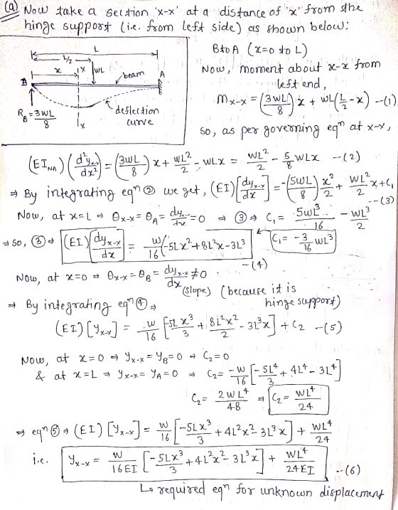
solution is as follows along with some basics:
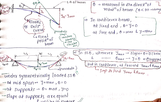
basic for deformation of beam with different supports:
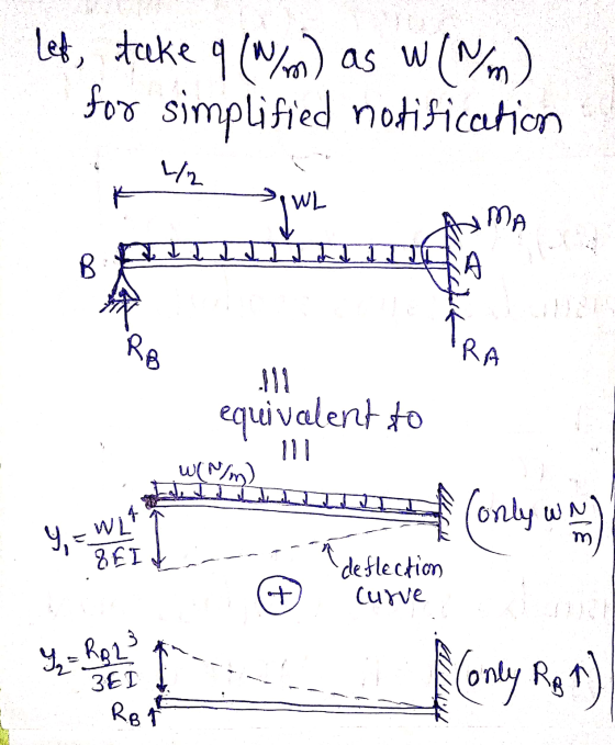
finding support reactions:
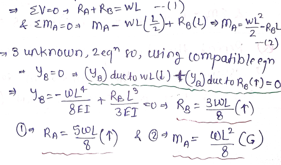
solution:
![(b) Now, at x = x= 1 / 2 3 4 x 4 = ? put x= 4² !! from equation 1. we get, Yemet [-52(4):41+4)=3()] WLA + 24 EI Y -5_4: 3 = @](http://img.homeworklib.com/questions/448b1b80-b98d-11eb-94b4-01b1c0963a1f.png?x-oss-process=image/resize,w_560) if i have done any mistake, i
believe that the procedure given above will help you.
if i have done any mistake, i
believe that the procedure given above will help you.
THANK YOU.
Add Answer to:
finaite element
3. Consider the beam-bending problem shown below. Using one element and assuming that the...
Please solve this question clearly and step by step. Thank you 2. A truss assembly shown...
 Please solve this question clearly and step by step.
Thank you
2. A truss assembly shown in Figure Q2 below is made of aluminum alloy that has a modulus of elasticity, E = 69 GPa. member is 225 mm2 The cross sectional area of each 4300 N (0, 40) m (40, 40) m 2 500 N 3 (0, 0) FIGURE Q2 Determine the global stiffness matrix for the truss assembly. a. [10 marks] Determine the displacement at node 3. b....
Please solve this question clearly and step by step.
Thank you
2. A truss assembly shown in Figure Q2 below is made of aluminum alloy that has a modulus of elasticity, E = 69 GPa. member is 225 mm2 The cross sectional area of each 4300 N (0, 40) m (40, 40) m 2 500 N 3 (0, 0) FIGURE Q2 Determine the global stiffness matrix for the truss assembly. a. [10 marks] Determine the displacement at node 3. b....
Use the stiffness method to analyse the structure shown below. For the beam ABC, E =...
 Use the stiffness method to analyse the structure shown below. For the beam ABC, E = 2 -108 kPa, A = 0,1 = 1.2e - 4 mº.. For the truss member DB, E = 200000000 kPa, A = 0.002 m². Also, take L = 6.5 m and o = 41 kN/m. 00 2 B с TIIL TE 3 Degrees of freedom D 2L Calculate the the bending moment at Joint B following the steps below: Part 1: Assemble the global...
Solve the following truss problem. All truss members are ANSI 2x2x0.25 hollow square tubes (with rounded...
 Solve the following truss problem. All truss members are ANSI 2x2x0.25 hollow square tubes (with rounded corners) for which the cross-section area is A-1.5891 in2. The material has a modulus of E-29E6 psi. Length of element 1 and 5 is L-20 inches, and length of element 3 and 6 is 2L 40 inches. 7 5 6 P-1000 lb 2. 1. Solve in an Excel spreadsheet using the truss element. Note that there are only four different element stiffness matrices (look...
For the beam elements shown (Node 1 is fixed and node 3 is a pin); the...
 For the beam elements shown (Node 1 is fixed and node 3 is a
pin);
the nodal displacements have been calculated in meters and radians
as:
V. V2 -0.001 V. 0.004 Let l 0.0001 m. and E 70 109 Nm: Neglecting the axial stiffness of the beam and using the interctions of a two-node beam element. (a) Find an equation for the slope of the beam in terms of the given nodal displacements and plot the slope diagram. (b) Find...
For the beam elements shown (Node 1 is fixed and node 3 is a
pin);
the nodal displacements have been calculated in meters and radians
as:
V. V2 -0.001 V. 0.004 Let l 0.0001 m. and E 70 109 Nm: Neglecting the axial stiffness of the beam and using the interctions of a two-node beam element. (a) Find an equation for the slope of the beam in terms of the given nodal displacements and plot the slope diagram. (b) Find...
Week 9, Question 1: Use the stiffness method to analyse the structure shown below. For the...
 Week 9, Question 1: Use the stiffness method to analyse the structure shown below. For the beam ABC, E = 2-108 kPa, A=00, I = 1.2e - 4 mº.. For the truss member DB, E = 200000000 kPa, A=0.002 m2. Also, take L=6.9 m and w=30 kN/m. Degrees of freedom l- _-2L Calculate the the bending moment at Joint B following the steps below: Part 1: Assemble the global structure stiffness matrix. Note that ABC is infinitely rigid in the...
Week 9, Question 1: Use the stiffness method to analyse the structure shown below. For the...
 Week 9, Question 1: Use the stiffness method to analyse the structure shown below. For the beam ABC, E = 2.108 kPa, A = 0,1 = 1.2e – 4 mº.. For the truss member DB, E = 200000000 kPa, A = 0.002 m². Also, take L = 4.8 m and a = 25 kN/m. 0 2 A B C III 7 L 3 4 Degrees of freedom D L -2L Calculate the the bending moment at Joint B following the...
Problem 3 (150 pts).Solve problem 5.64 using a beam/frame element as well as a 3D. Use standard s...
Problem 3 (150 pts).Solve problem 5.64 using a beam/frame element as well as a 3D. Use standard steel properties in Workbench, E=29E6 etc, Cross-section 0.3 by 0.2, inner radius 1.85 in, outer radius 2.15 in, thickness = 0.2 in Obtain the following for an imposed gap of 0.2 inch d. Compare the three sets of results, and COMMENT on possible reasons for any differences (element assumptions/shape functions, boundary conditions, number of elements, etc). Note that there are different displacement functions...
Problem 1.1 Consider the beam bending problem below 2 Po Consider the beam to be homogenous...
 Problem 1.1 Consider the beam bending problem below 2 Po Consider the beam to be homogenous and linearly elastic, with length L, stiffness E, and moment of inertia I. The beam is cantilevered at x = 0 an d is supported by a linear spring of stiffness k at x-L. A uniformly distributed transverse load po (N/m) is applied to the upper surface a) Write and solve the GDE to obtain the exact solution for the deflection w(x) of this...
3. Consider a two-d.o.f bar element, as shown below, but let the cross-sectional area vary linearly...
 3. Consider a two-d.o.f bar element, as shown below, but let the cross-sectional area vary linearly with x from Ag atx-0 to 2Ao at x - L Use the direct method to generate the element stiffness matrix. Suggestion: first compute the elongation produced by the axial force. a. b Use the formal procedure to generate the stiffness matrix. Suggestion use Eqn. 2.2.6 c The stiffness matrices of parts a and b do not agree. Why? ก็เ«F21 A E Fiz al...
Problem 1 Consider the bar shown below with a cross-sectional area A, 1.2 m2, and Young's...
 Problem 1 Consider the bar shown below with a cross-sectional area A, 1.2 m2, and Young's modulus E-200 X 109 Pa. Ifq,-0.02 m and q,-0.025 m determine the following (by hand calculation) (a) the displacement at point P., (b) the strain E and stress σ (e) the element stiffness matrix, and (d) the strain energy in the element 91 *p 20 m x,-15 m x,-23 m Problem 2. Consider a finite element with shape functions N1) and N2(Š) used to...
 Please solve this question clearly and step by step.
Thank you
2. A truss assembly shown in Figure Q2 below is made of aluminum alloy that has a modulus of elasticity, E = 69 GPa. member is 225 mm2 The cross sectional area of each 4300 N (0, 40) m (40, 40) m 2 500 N 3 (0, 0) FIGURE Q2 Determine the global stiffness matrix for the truss assembly. a. [10 marks] Determine the displacement at node 3. b....
Please solve this question clearly and step by step.
Thank you
2. A truss assembly shown in Figure Q2 below is made of aluminum alloy that has a modulus of elasticity, E = 69 GPa. member is 225 mm2 The cross sectional area of each 4300 N (0, 40) m (40, 40) m 2 500 N 3 (0, 0) FIGURE Q2 Determine the global stiffness matrix for the truss assembly. a. [10 marks] Determine the displacement at node 3. b....
 Use the stiffness method to analyse the structure shown below. For the beam ABC, E = 2 -108 kPa, A = 0,1 = 1.2e - 4 mº.. For the truss member DB, E = 200000000 kPa, A = 0.002 m². Also, take L = 6.5 m and o = 41 kN/m. 00 2 B с TIIL TE 3 Degrees of freedom D 2L Calculate the the bending moment at Joint B following the steps below: Part 1: Assemble the global...
 Solve the following truss problem. All truss members are ANSI 2x2x0.25 hollow square tubes (with rounded corners) for which the cross-section area is A-1.5891 in2. The material has a modulus of E-29E6 psi. Length of element 1 and 5 is L-20 inches, and length of element 3 and 6 is 2L 40 inches. 7 5 6 P-1000 lb 2. 1. Solve in an Excel spreadsheet using the truss element. Note that there are only four different element stiffness matrices (look...
 For the beam elements shown (Node 1 is fixed and node 3 is a
pin);
the nodal displacements have been calculated in meters and radians
as:
V. V2 -0.001 V. 0.004 Let l 0.0001 m. and E 70 109 Nm: Neglecting the axial stiffness of the beam and using the interctions of a two-node beam element. (a) Find an equation for the slope of the beam in terms of the given nodal displacements and plot the slope diagram. (b) Find...
For the beam elements shown (Node 1 is fixed and node 3 is a
pin);
the nodal displacements have been calculated in meters and radians
as:
V. V2 -0.001 V. 0.004 Let l 0.0001 m. and E 70 109 Nm: Neglecting the axial stiffness of the beam and using the interctions of a two-node beam element. (a) Find an equation for the slope of the beam in terms of the given nodal displacements and plot the slope diagram. (b) Find...
 Week 9, Question 1: Use the stiffness method to analyse the structure shown below. For the beam ABC, E = 2-108 kPa, A=00, I = 1.2e - 4 mº.. For the truss member DB, E = 200000000 kPa, A=0.002 m2. Also, take L=6.9 m and w=30 kN/m. Degrees of freedom l- _-2L Calculate the the bending moment at Joint B following the steps below: Part 1: Assemble the global structure stiffness matrix. Note that ABC is infinitely rigid in the...
 Week 9, Question 1: Use the stiffness method to analyse the structure shown below. For the beam ABC, E = 2.108 kPa, A = 0,1 = 1.2e – 4 mº.. For the truss member DB, E = 200000000 kPa, A = 0.002 m². Also, take L = 4.8 m and a = 25 kN/m. 0 2 A B C III 7 L 3 4 Degrees of freedom D L -2L Calculate the the bending moment at Joint B following the...
 Problem 1.1 Consider the beam bending problem below 2 Po Consider the beam to be homogenous and linearly elastic, with length L, stiffness E, and moment of inertia I. The beam is cantilevered at x = 0 an d is supported by a linear spring of stiffness k at x-L. A uniformly distributed transverse load po (N/m) is applied to the upper surface a) Write and solve the GDE to obtain the exact solution for the deflection w(x) of this...
 3. Consider a two-d.o.f bar element, as shown below, but let the cross-sectional area vary linearly with x from Ag atx-0 to 2Ao at x - L Use the direct method to generate the element stiffness matrix. Suggestion: first compute the elongation produced by the axial force. a. b Use the formal procedure to generate the stiffness matrix. Suggestion use Eqn. 2.2.6 c The stiffness matrices of parts a and b do not agree. Why? ก็เ«F21 A E Fiz al...
 Problem 1 Consider the bar shown below with a cross-sectional area A, 1.2 m2, and Young's modulus E-200 X 109 Pa. Ifq,-0.02 m and q,-0.025 m determine the following (by hand calculation) (a) the displacement at point P., (b) the strain E and stress σ (e) the element stiffness matrix, and (d) the strain energy in the element 91 *p 20 m x,-15 m x,-23 m Problem 2. Consider a finite element with shape functions N1) and N2(Š) used to...
Most questions answered within 3 hours.
-
1. Why are the advantages and disadvantages of object-oriented
databases? 2. What are data marts? How...
asked 9 minutes ago -
A Porsche challenges a Honda to a 4.00×10²m race. Because the
Porsche's acceleration of 3.30 m/s2...
asked 10 minutes ago -
A sample of C3H8 has 1.60×1024 H atoms.
How many carbon atoms does the sample contain?...
asked 1 hour ago -
How many unique codes are possibly formed from two characters,
where the first character can be...
asked 32 minutes ago -
A concentration cell is built based on the reaction:
2H+ + 2e- ----> H2
The pH...
asked 28 minutes ago -
what is the ph of the following solutions?
150 g NH4CI dissolved into 10.0 mL of...
asked 39 minutes ago -
A projectile is launched with an initial speed of 40 m/s at an
angle of 25°...
asked 22 minutes ago -
1. Using a function, display the customer who has the highest
credit limit. Display the customer...
asked 30 minutes ago -
A spatially uniform electric field varies in time according
to E = Eo + 3000 t,...
asked 56 minutes ago -
An electric power station that operates at 25 kV and uses a 20:1
step-up ideal transformer...
asked 49 minutes ago -
1. If 0.02% of a 0.6 M weak acid ionizes in a solution, what is
the...
asked 36 minutes ago -
The College of Business at Northeast College is accumulating
data as a first step in the...
asked 42 minutes ago