![c ω Flla tilar//cv users/matrullounleadsESE111 1+un t-5+Hybnd +Assignment%20[2].pdt MULTIPLE CHOICE. Choose the one alternative that best completes the statement or answers the question R-252 Eigure 13-1 13) Flnd the voltage acos he capocitor in Figure 13-1 A) 0.633 V 6)-1.9V C) 537 D) 10.7 14) If the mistance increases in Fipre. 13-1, the impedance A) deuses 15) As the ncquency approaches the acsonant eqncy in Figure 13-1, tce vollagc os he est B) increases C) rmaih Figure 13-2 16) If the capaciter opens in Figure 13-2 the current A) decreses to 3) remains the same C) contiruegto ศ0w, but the circuit would not be resonant](http://img.homeworklib.com/questions/e29f7770-bb04-11eb-9c42-77e312176958.png?x-oss-process=image/resize,w_560)
Figure 13-1
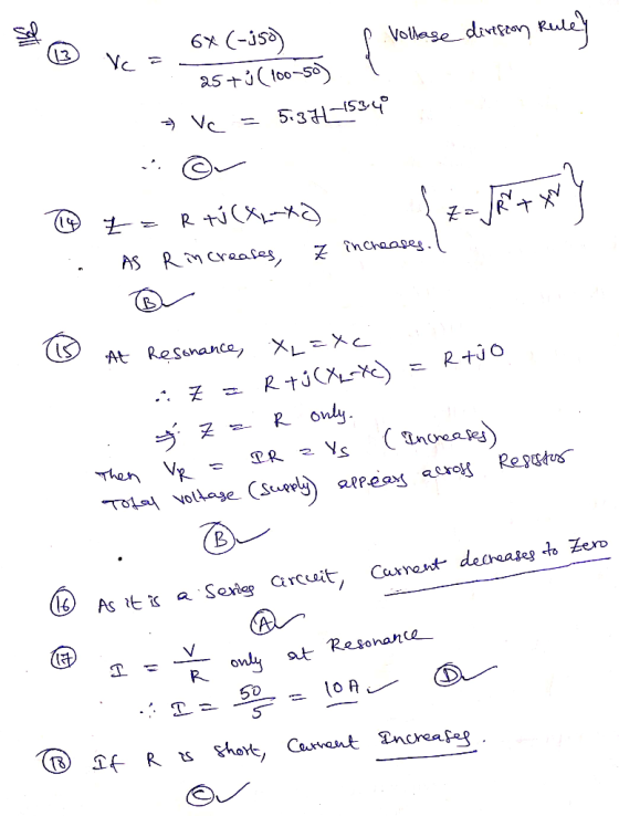
13) Find the voltage across the capacitor in Figure 13-1.
A) 0.633 V B) -4.9 V C) 5.37 V D) 10.7 V
14) If the resistance increases in Figure 13-1, the impedance ________.
A) decreases B) increases C) remains the same D) becomes zero
15) As the frequency approaches the resonant frequency in Figure 13-1, the voltage across the resistor ________.
A) becomes increasingly unstable B) increases
C) remains the same D) decreases
Figure 13-2
16) If the capacitor opens in Figure 13-2, the current ________.
A) decreases to zero
B) remains the same
C) continues to flow, but the circuit would not be resonant
D) increases because of the inductor
17) At resonance, the current in Figure 13-2 is ________.
A) 1.66 4 B) 1.66 mA C) 10 mA D) 10 A
18) If the resistor shorts in Figure 13-2, the current ________.
A) decreases B) continues, but the circuit would not be
resonant
C) increases D) does not change
Homework Answers
Add Answer to:
Figure 13-1
13) Find the voltage across the capacitor in Figure 13-1.
A) 0.633 V B)...
(a) Find the current across the resistor. (b) Find the current across the inductor. (c) What...
 (a) Find the current across the resistor.
(b) Find the current across the inductor.
(c) What is the magnitude of the total current?
(d) Find the impedance of the circuit.
(e) What is the phase angle between the current and the
voltage?
Consider the parallel RL circuit shown in Figure 12.11.4 V(t) R &L Figure 12.11.4 Parallel RL circuit The AC voltage source is V(t)Vo, sin ot
(a) Find the current across the resistor.
(b) Find the current across the inductor.
(c) What is the magnitude of the total current?
(d) Find the impedance of the circuit.
(e) What is the phase angle between the current and the
voltage?
Consider the parallel RL circuit shown in Figure 12.11.4 V(t) R &L Figure 12.11.4 Parallel RL circuit The AC voltage source is V(t)Vo, sin ot
X1 30 R-50 50 V X-30 0 Figure 13-2 21) If the resistance increases in Figure...
 X1 30 R-50 50 V X-30 0 Figure 13-2 21) If the resistance increases in Figure 13-2, the bandwidth 22) What is the bandwidth of a resonant circuit if its resonant frequency is 14.2 MHz, the inductive reactance is 3.5 kQ and the coil's resistance is 8 ohm? 23) The output voltage of a circuit at 70.7 % of its maximum level measured in dB is: 24) Why does a resistive load increase the bandwidth of a given band-pass filter?...
QUESTION 13 ECE 231 Circuit Analysis II --Question 3: Calculate the voltage across inductor V, for...
 QUESTION 13 ECE 231 Circuit Analysis II --Question 3: Calculate the voltage across inductor V, for the circuit shown in the figure below if the total impedance Z = 1.8kQ2 + j1.4kQ2 = 2.28kQ2Z37.87° R = 1.8K22 XL = 2 kN Xc = 0.6 k 2 000 16 + + UR + 01 + VC E = 4.242260° V 1 OVL - 3.72 V 2112.13 OVL - 7.32 V 2-112.13 OVL - 2.73 V 2112.13 OVL - 3.72 V 2112.13
51 For the low pass filter in figure 5 find: [2 Marks] Cutoff(Critical) frequency Output Voltage...
 51 For the low pass filter in figure 5 find: [2 Marks] Cutoff(Critical) frequency Output Voltage at Cut off frequency 4.7 k C 1020 V 10 F Figure 5 6 Find at resonance from figure 5: [3 Marks] a. Resonant Frequency. d. Quality factor. e. Bandwidth b. Impedance at resonance f. Current at the half power Current at resonance. c. Vs 10 v L-1mH C-10uF R-102 C L R V Figure 5
A resistor and capacitor are connected in series across an ac generator. The voltage of the...
 A resistor and capacitor are connected in series across an ac generator. The voltage of the generator is given by V() = Vocos(wt), where Vo = 120V,w = 120x rad/s, R = 55082, and C = 7.54F. (a) What is the magnitude of the impedance of the RC circuit? (b) What is the amplitude of the current through the resistor? (e) What is the phase difference between the voltage and current? The magnitude of the impedance is The amplitude of...
In the figure bclow, a generator with an adustable frequency of oscillation is connected to resistance...
 In the figure bclow, a generator with an adustable frequency of oscillation is connected to resistance R 860 n ind tances L1 0 mH and L2 2 m a capac tances C 8 00니 C S a and -7.00 i (a) What is the resonant frequency of the circuit? Hz (b) What happens to the resonant frequency if R is increased? It increases It decreases It stays the same. (c) What happens to the resonant frequency it L1 is increased?...
A resistor and capacitor are connected in series across an ac generator. The voltage of the...
 A resistor and capacitor are connected in series across an ac generator. The voltage of the generator is given by V(0) = Vocos(wt), where VO = 120V, w = 120+ rad/s, R=55092, and C = 3pF. (a) What is the magnitude of the impedance of the RC circuit (b) What is the amplitude of the current through the resistor? (c) What is the phase difference between the voltage and current? The magnitude of the impedance is 1041.3 22. The amplitude...
The LCR circuit in the figure below is driven by a voltage source with VAC =...
 The LCR circuit in the figure below is driven by a voltage
source with VAC = Vmax sin(2(pi)ft), where Vmax = 12 V, R = 280
ohms, and C = 31 nF. (a) If the resonant frequency is
fres = 99 MHz,
what is L? (b) What is the amplitude (the
peak value) of the current when
f = fres?
The LCR circuit in the figure below is driven by a voltage source with VAC = Vmax sin(2(pi)ft), where Vmax...
The LCR circuit in the figure below is driven by a voltage
source with VAC = Vmax sin(2(pi)ft), where Vmax = 12 V, R = 280
ohms, and C = 31 nF. (a) If the resonant frequency is
fres = 99 MHz,
what is L? (b) What is the amplitude (the
peak value) of the current when
f = fres?
The LCR circuit in the figure below is driven by a voltage source with VAC = Vmax sin(2(pi)ft), where Vmax...
a. b. C. A 250-ohm resistor, a 0.450 H inductor, and a 6.45 uF capacitor are...
 a. b. C. A 250-ohm resistor, a 0.450 H inductor, and a 6.45 uF capacitor are connected in series across an emf with a 36.0 volt amplitude and an angular frequency of 260 rad/s. What is the impedance? What is the current amplitude? What is the phase angle between the voltage and current? Does the voltage lag or lead? What are the voltage amplitudes across the resistor, inductor and capacitor individually? What is the power? f. What is the resonant...
A circuit consists of a resistor, capacitor, and inductor connected in series to an AC source....
A circuit consists of a resistor, capacitor, and inductor connected in series to an AC source. As the source frequency increases, the current in the circuit decreases. Which statement about the circuit is NOT correct as the source frequency increases? a) The inductive reactance increases. b) The circuit is said to become more capacitive than inductive. c) The total power from the source decreases. d) The impedance of the circuit increases. e) The phase angle for the circuit becomes more...
 (a) Find the current across the resistor.
(b) Find the current across the inductor.
(c) What is the magnitude of the total current?
(d) Find the impedance of the circuit.
(e) What is the phase angle between the current and the
voltage?
Consider the parallel RL circuit shown in Figure 12.11.4 V(t) R &L Figure 12.11.4 Parallel RL circuit The AC voltage source is V(t)Vo, sin ot
(a) Find the current across the resistor.
(b) Find the current across the inductor.
(c) What is the magnitude of the total current?
(d) Find the impedance of the circuit.
(e) What is the phase angle between the current and the
voltage?
Consider the parallel RL circuit shown in Figure 12.11.4 V(t) R &L Figure 12.11.4 Parallel RL circuit The AC voltage source is V(t)Vo, sin ot
 X1 30 R-50 50 V X-30 0 Figure 13-2 21) If the resistance increases in Figure 13-2, the bandwidth 22) What is the bandwidth of a resonant circuit if its resonant frequency is 14.2 MHz, the inductive reactance is 3.5 kQ and the coil's resistance is 8 ohm? 23) The output voltage of a circuit at 70.7 % of its maximum level measured in dB is: 24) Why does a resistive load increase the bandwidth of a given band-pass filter?...
 QUESTION 13 ECE 231 Circuit Analysis II --Question 3: Calculate the voltage across inductor V, for the circuit shown in the figure below if the total impedance Z = 1.8kQ2 + j1.4kQ2 = 2.28kQ2Z37.87° R = 1.8K22 XL = 2 kN Xc = 0.6 k 2 000 16 + + UR + 01 + VC E = 4.242260° V 1 OVL - 3.72 V 2112.13 OVL - 7.32 V 2-112.13 OVL - 2.73 V 2112.13 OVL - 3.72 V 2112.13
 51 For the low pass filter in figure 5 find: [2 Marks] Cutoff(Critical) frequency Output Voltage at Cut off frequency 4.7 k C 1020 V 10 F Figure 5 6 Find at resonance from figure 5: [3 Marks] a. Resonant Frequency. d. Quality factor. e. Bandwidth b. Impedance at resonance f. Current at the half power Current at resonance. c. Vs 10 v L-1mH C-10uF R-102 C L R V Figure 5
 A resistor and capacitor are connected in series across an ac generator. The voltage of the generator is given by V() = Vocos(wt), where Vo = 120V,w = 120x rad/s, R = 55082, and C = 7.54F. (a) What is the magnitude of the impedance of the RC circuit? (b) What is the amplitude of the current through the resistor? (e) What is the phase difference between the voltage and current? The magnitude of the impedance is The amplitude of...
 In the figure bclow, a generator with an adustable frequency of oscillation is connected to resistance R 860 n ind tances L1 0 mH and L2 2 m a capac tances C 8 00니 C S a and -7.00 i (a) What is the resonant frequency of the circuit? Hz (b) What happens to the resonant frequency if R is increased? It increases It decreases It stays the same. (c) What happens to the resonant frequency it L1 is increased?...
 A resistor and capacitor are connected in series across an ac generator. The voltage of the generator is given by V(0) = Vocos(wt), where VO = 120V, w = 120+ rad/s, R=55092, and C = 3pF. (a) What is the magnitude of the impedance of the RC circuit (b) What is the amplitude of the current through the resistor? (c) What is the phase difference between the voltage and current? The magnitude of the impedance is 1041.3 22. The amplitude...
 The LCR circuit in the figure below is driven by a voltage
source with VAC = Vmax sin(2(pi)ft), where Vmax = 12 V, R = 280
ohms, and C = 31 nF. (a) If the resonant frequency is
fres = 99 MHz,
what is L? (b) What is the amplitude (the
peak value) of the current when
f = fres?
The LCR circuit in the figure below is driven by a voltage source with VAC = Vmax sin(2(pi)ft), where Vmax...
The LCR circuit in the figure below is driven by a voltage
source with VAC = Vmax sin(2(pi)ft), where Vmax = 12 V, R = 280
ohms, and C = 31 nF. (a) If the resonant frequency is
fres = 99 MHz,
what is L? (b) What is the amplitude (the
peak value) of the current when
f = fres?
The LCR circuit in the figure below is driven by a voltage source with VAC = Vmax sin(2(pi)ft), where Vmax...
 a. b. C. A 250-ohm resistor, a 0.450 H inductor, and a 6.45 uF capacitor are connected in series across an emf with a 36.0 volt amplitude and an angular frequency of 260 rad/s. What is the impedance? What is the current amplitude? What is the phase angle between the voltage and current? Does the voltage lag or lead? What are the voltage amplitudes across the resistor, inductor and capacitor individually? What is the power? f. What is the resonant...
Most questions answered within 3 hours.
-
What is the chemical equation (with states) for this
reaction in balanced and unbalanced form?
In...
asked 17 seconds ago -
In engineering and product design, it is important to consider
the weights of people so that...
asked 5 minutes ago -
The first-order decomposition of N2O5 at 328 K has a rate
constant of 1.70 × 10⁻³...
asked 6 minutes ago -
Do you believe that some things that fall into the category of
“pseudoscience” are worth believing...
asked 29 minutes ago -
A 0.100-kg, 59.6-cm-long uniform bar has a small 0.070-kg mass
glued to its left end and...
asked 21 minutes ago -
Direct Labor Variances
The following data relate to labor cost for production of 4,600
cellular telephones:...
asked 34 minutes ago -
On July 27, 2018, shareholders of the Walt Disney Company and
21st Century Fox agreed to...
asked 13 minutes ago -
Write a brief response, 30-90-words, for each question below. 1.
In your own words, define “Auditing.”...
asked 18 minutes ago -
Water flows through a 8-foot wide and 4-foot tall rectangular
channel. If the desired flow rate...
asked 25 minutes ago -
Cruz Video Center accumulates the following cost and net
realizable data at December 31.
Cameras $14,700...
asked 29 minutes ago -
1. Describe the differences between management in the nonprofit
sector and management in other sectors. How...
asked 36 minutes ago -
Identify the location of the following corresponding operand if
the address field in an instruction contains...
asked 37 minutes ago