A common demonstration of inductance employs a circuit such as the one shown in the figure (Figure 1) . Switch S is closed, and the light bulb (represented by resistance R1) just barely glows. After a period of time, switch S is opened, and the bulb lights up brightly for a short period of time. To understand this effect, think of an inductor as a device that imparts an "inertia" to the current, preventing a discontinuous change in the current through it.
A)
Derive, as explicit function of time, expression for i1 (the current through the light bulb) after switch S is closed.
Express your answer in terms of the variables E, R1, R2, L, and t.
B)
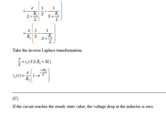
Derive, as explicit function of time, expression for i2 (the current through the resistor R2) after switch Sis closed.
Express your answer in terms of the variables E, R1, R2, L, and t.
C)
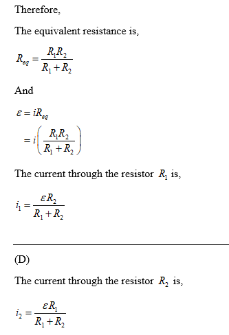
After a long period of time, the current i1 reaches their steady-state value. Obtain expression for this steady-state currents.
Express your answer in terms of the variables E, R1, R2, L, and t.
D)
After a long period of time, the current i2 reaches their steady-state value. Obtain expression for this steady-state currents.
Express your answer in terms of the variables E, R1, R2, L, and t.
E)
Switch S is now opened. Obtain an expression for the current through the light bulb inductor as an explicit function of time.
Express your answer in terms of the variables E, R1, R2, L, and t.
F)
Switch S is now opened. Obtain an expression for the current through the inductor as an explicit function of time.
Express your answer in terms of the variables E, R1, R2, L, and t.

Homework Answers


Add Answer to:
A common demonstration of inductance employs a circuit such as
the one shown in the figure...
IP The switch in the circuit shown in the figure(Figure 1) is open initially. Part A...
 IP The switch in the circuit shown in the figure(Figure 1) is
open initially.
Part A Find the current in the circuit a long
time after the switch is closed. Express your answer in terms of
some or all of the variables E, R1, R2, and
L.
Part B. Describe the behavior of the lightbulb
from the time the switch is closed until the current reaches the
value found in part A.
Part C. Now, suppose the switch is opened...
IP The switch in the circuit shown in the figure(Figure 1) is
open initially.
Part A Find the current in the circuit a long
time after the switch is closed. Express your answer in terms of
some or all of the variables E, R1, R2, and
L.
Part B. Describe the behavior of the lightbulb
from the time the switch is closed until the current reaches the
value found in part A.
Part C. Now, suppose the switch is opened...
(3) The RL circuit shown in Figure 3 has a switch that is closed att 0....
 (3) The RL circuit shown in Figure 3 has a switch that is closed att 0. Assume that the circuit has reached steady state prior to the switch closing. You are given R1 1 kQ, R2-10 kQ, R3-R4-100 k2, L 10 mH, Vs-5 V. (a) [15 pts] Calculate the steady-state inductor current before the switch is closed (b) [16 pts] Give the differential equation as an expression of the inductor current fort>0 (i.e. write the differential equation) (c) 13 pts]...
A circuit is constructed with two resistors and one inductor as shown in the Figure below....
 A circuit is constructed with two resistors and one inductor as shown in the Figure below. The values for the resistors are: R1 = 2.50 and R2 = 4.5 0. The battery voltage is V = 12 V. The switch S is initially open. S R V R2 L 000 1) After the switch has been opened a long time, it is closed. What is the magnitude of the voltage across L immediately after the switch is closed? O 7.7...
In the circuit shown in the figure, the battery is ideal, = 12.6 V, L =...
 In the circuit shown in the
figure, the battery is ideal, = 12.6 V, L = 11.3 mH, R1 = 11.1 ?,
and R2 = 20.1 ?. The switch has been open for a long time before it
is closed at t = 0. At what rate is the current in the inductor
changing (a) immediately after the switch is closed and (b) when
the current in the battery is 0.530 A? (c) What is the current (in
A) in...
In the circuit shown in the
figure, the battery is ideal, = 12.6 V, L = 11.3 mH, R1 = 11.1 ?,
and R2 = 20.1 ?. The switch has been open for a long time before it
is closed at t = 0. At what rate is the current in the inductor
changing (a) immediately after the switch is closed and (b) when
the current in the battery is 0.530 A? (c) What is the current (in
A) in...
A circuit is constructed with four resistors, one inductor, one battery and a switch as shown....
 A circuit is constructed with four resistors, one inductor, one battery and a switch as shown. The values for the resistors are: R1-R2-76 Ω, R3-105 Ω and R4-810. The inductance is L-478 mH and the battery voltage is V-24 V 1) The switch has been open for a long time when at time t - o, the switch is closed. What is 11(0), the magnitude of the current through the resistor R1 just after the switch is closed? A uIii...
(1) [21 pts] The RL circuit shown in Figures 1 and 2 has a switch. You...
 (1) [21 pts] The RL circuit shown in Figures 1 and 2 has a switch. You are given I1 =10 mA, R1=R2=1 ks2, and L=10 mH. (a) [3 pts] Using Figure 1, with an open switch, calculate the steady state current through the inductor. (b) [12 pts) Using Figure 2, with a closed switch, derive the differential equation as an expression of the inductor current. (c) [2 pts] Using your answer to Part (b), calculate the time constant. (d) [4...
A circuit is constructed with four resistors, one inductor, one battery and a switch as shown....
 A circuit is constructed with four resistors, one inductor, one battery and a switch as shown. The values for the resistors are: R1 = R2 = 49 Q, R = 105 Q and Ra = 142 . The inductance is L = 354 mH and the battery voltage is V = 12 V. The positive terminal of the battery is indicated with a + sign. "TII Luni 1) The switch has been open for a long time when at time...
Problem 4 In the circuit shown below, the switch has been opened for a very long...
 Problem 4 In the circuit shown below, the switch has been opened for a very long time prior to t= 0 and closes at t = 0 and remains closed for a long time. Please find: a) i (0), vc(ot), b) the steady-state voltage across the capacitor in terms of Us, Rı, and R2 c) the steady state current through the inductor in terms of Us, Ry, and R2 d) Write the differential equation for it) in terms of Vs,...
A circuit is constructed with four resistors, one inductor, one battery and a switch as shown. The values for the resistors are: R1 = R2 = 48 Ω, R3 = 100 Ω and R4 = 130 Ω.
 A circuit is constructed with four resistors, one inductor, one battery and a switch as shown. The values for the resistors are: R1 = R2 = 48 Ω, R3 = 100 Ω and R4 = 130 Ω. The inductance is L = 330 mH and the battery voltage is V = 12 V. The positive terminal of the battery is indicated with a + sign.1)The switch has been open for a long time when at time t = 0, the...
 IP The switch in the circuit shown in the figure(Figure 1) is
open initially.
Part A Find the current in the circuit a long
time after the switch is closed. Express your answer in terms of
some or all of the variables E, R1, R2, and
L.
Part B. Describe the behavior of the lightbulb
from the time the switch is closed until the current reaches the
value found in part A.
Part C. Now, suppose the switch is opened...
IP The switch in the circuit shown in the figure(Figure 1) is
open initially.
Part A Find the current in the circuit a long
time after the switch is closed. Express your answer in terms of
some or all of the variables E, R1, R2, and
L.
Part B. Describe the behavior of the lightbulb
from the time the switch is closed until the current reaches the
value found in part A.
Part C. Now, suppose the switch is opened...
 (3) The RL circuit shown in Figure 3 has a switch that is closed att 0. Assume that the circuit has reached steady state prior to the switch closing. You are given R1 1 kQ, R2-10 kQ, R3-R4-100 k2, L 10 mH, Vs-5 V. (a) [15 pts] Calculate the steady-state inductor current before the switch is closed (b) [16 pts] Give the differential equation as an expression of the inductor current fort>0 (i.e. write the differential equation) (c) 13 pts]...
 A circuit is constructed with two resistors and one inductor as shown in the Figure below. The values for the resistors are: R1 = 2.50 and R2 = 4.5 0. The battery voltage is V = 12 V. The switch S is initially open. S R V R2 L 000 1) After the switch has been opened a long time, it is closed. What is the magnitude of the voltage across L immediately after the switch is closed? O 7.7...
 In the circuit shown in the
figure, the battery is ideal, = 12.6 V, L = 11.3 mH, R1 = 11.1 ?,
and R2 = 20.1 ?. The switch has been open for a long time before it
is closed at t = 0. At what rate is the current in the inductor
changing (a) immediately after the switch is closed and (b) when
the current in the battery is 0.530 A? (c) What is the current (in
A) in...
In the circuit shown in the
figure, the battery is ideal, = 12.6 V, L = 11.3 mH, R1 = 11.1 ?,
and R2 = 20.1 ?. The switch has been open for a long time before it
is closed at t = 0. At what rate is the current in the inductor
changing (a) immediately after the switch is closed and (b) when
the current in the battery is 0.530 A? (c) What is the current (in
A) in...
 A circuit is constructed with four resistors, one inductor, one battery and a switch as shown. The values for the resistors are: R1-R2-76 Ω, R3-105 Ω and R4-810. The inductance is L-478 mH and the battery voltage is V-24 V 1) The switch has been open for a long time when at time t - o, the switch is closed. What is 11(0), the magnitude of the current through the resistor R1 just after the switch is closed? A uIii...
 (1) [21 pts] The RL circuit shown in Figures 1 and 2 has a switch. You are given I1 =10 mA, R1=R2=1 ks2, and L=10 mH. (a) [3 pts] Using Figure 1, with an open switch, calculate the steady state current through the inductor. (b) [12 pts) Using Figure 2, with a closed switch, derive the differential equation as an expression of the inductor current. (c) [2 pts] Using your answer to Part (b), calculate the time constant. (d) [4...
 A circuit is constructed with four resistors, one inductor, one battery and a switch as shown. The values for the resistors are: R1 = R2 = 49 Q, R = 105 Q and Ra = 142 . The inductance is L = 354 mH and the battery voltage is V = 12 V. The positive terminal of the battery is indicated with a + sign. "TII Luni 1) The switch has been open for a long time when at time...
 Problem 4 In the circuit shown below, the switch has been opened for a very long time prior to t= 0 and closes at t = 0 and remains closed for a long time. Please find: a) i (0), vc(ot), b) the steady-state voltage across the capacitor in terms of Us, Rı, and R2 c) the steady state current through the inductor in terms of Us, Ry, and R2 d) Write the differential equation for it) in terms of Vs,...
Most questions answered within 3 hours.
-
The average length of time between arrivals at a turnpike
toll-booth is 26 seconds. What is...
asked 1 hour ago -
(a) A piston at 6.1 atm contains a gas that occupies a volume of
3.5 L....
asked 2 hours ago -
Please answer true or false. Words
cannot be changed or added in to make it true...
asked 2 hours ago -
An empty test tube weighs 15.923 grams. Then,
MgCl2•6H2O is added into the test tube. After...
asked 2 hours ago -
Assume memory access is 10 units of time and disk access is
10000 units of time....
asked 2 hours ago -
1. Are all good samples random?
2. Magazines often report surveys giving statistics such as “63%...
asked 3 hours ago -
Under all the various types of market structures, firms
must eventually earn some economic profits for...
asked 2 hours ago -
Consider the following fitness regime for a single locus trait
with two co-dominant alleles: w11 =...
asked 2 hours ago -
A large cable company reports the following.
80% of its customers subscribe to its cable TV...
asked 3 hours ago -
Please answer the question in brief.
Discuss the role of ERP in organizations. Are ERP tools...
asked 2 hours ago -
Discuss the pros and cons of collaborative software such
as SameTime. Does it increase productivity? What...
asked 3 hours ago -
Buying your in-laws a gift because it’s expected is
due to the ____________ motive of gift-giving....
asked 3 hours ago