
Homework Answers

Add Answer to:
Draw the shear and bending-moment diagrams for the beams and
loadings.
24kN/m 64kN・m S250×2 12ml-12--12ml 40kN...
find 1) Draw shear force and bending moment diagrams for the beams subjected to the loadings...
 find
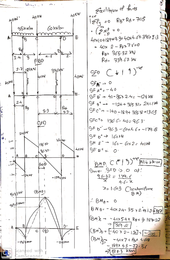
1) Draw shear force and bending moment diagrams for the beams subjected to the loadings shown below. Please show all your work SEN 25 N/m 45KM 10KN KN 15 2m 1 Im 2 3 m
find
1) Draw shear force and bending moment diagrams for the beams subjected to the loadings shown below. Please show all your work SEN 25 N/m 45KM 10KN KN 15 2m 1 Im 2 3 m
Draw the shear and bending-moment diagrams for the beams and loadings shown (indicate position and magnitude...
 Draw the shear and bending-moment diagrams for the beams and
loadings shown (indicate position and magnitude of the maximum and
minimum shear and bending moment values in the diagrams):
P-2400 lb-(000 -400 bt 91- RB 24 ft
Draw the shear and bending-moment diagrams for the beams and
loadings shown (indicate position and magnitude of the maximum and
minimum shear and bending moment values in the diagrams):
P-2400 lb-(000 -400 bt 91- RB 24 ft
6. For the beams and loading shown draw the shear and bending-moment diagrams and then find...
 6. For the beams and loading shown draw the shear and bending-moment diagrams and then find the maximum absolute values of the shear and bending moment. 2500 lb 60 KN 25 kN/m 500 lb /ft A c Di 5-3 ft--3--3-1-3ft Ć D -3 ft 3 ft — —3 ft 3 ft — Tam-kata2 122 m- 1 m
For the beams of problems 6.2-6.16, draw the shear force and bending moment diagrams and find...
 For the beams of problems 6.2-6.16, draw the shear force and
bending moment
diagrams and find the maximum shear force, maximum bending moment
and
point(s) of contraflexure (PCF).
7 kN 6 kN/m 4 kN/m B 2 m e C D E 24 kN 1,5m 7590.0.751 Figure 6.41
For the beams of problems 6.2-6.16, draw the shear force and
bending moment
diagrams and find the maximum shear force, maximum bending moment
and
point(s) of contraflexure (PCF).
7 kN 6 kN/m 4 kN/m B 2 m e C D E 24 kN 1,5m 7590.0.751 Figure 6.41
Draw the shear force and bending moment diagrams for the beams shown 5 kN 3 kN/m...
 Draw the shear force and bending moment diagrams for the beams
shown
5 kN 3 kN/m 3 m 1.5 m1.5mFig. 4 3 m
Draw the shear force and bending moment diagrams for the beams
shown
5 kN 3 kN/m 3 m 1.5 m1.5mFig. 4 3 m
Problem Determine the reactions and draw the shear and bending moment diagrams for the beams shown...
 Problem Determine the reactions and draw the shear and bending moment diagrams for the beams shown in Figs. P16.8-P16.14 by using the moment-distribution method 120 kN 120 kN 150 kN m--4 21 E 200 GPa 1- 500 (106 mm
Draw shear force and bending moment diagrams for the beams shown below. Use matrix methods 25kN...
 Draw shear force and bending moment diagrams for the beams shown below. Use matrix methods 25kN 25 kN SkN/m | 1,1 C(Hinge) 1,1 | 1, 11 1,15
1- Draw shear and bending moment diagrams for the following simply supported beams, find the location...
 1- Draw shear and bending moment diagrams for the following simply supported beams, find the location and magnitude of maximum moment for each one. Show all of your calculations. 1 kN 4 KN 2 kN (7marks) 5 kN/m TITIT 40 70 70 40 40 60 A B с TI G DE All distances in cm II- 3kN 1.5 kN/m A B с RA 6m 3m Rc
4. Draw shear force & bending moment diagrams for the shown beams 30 kN 20 kN...
 4. Draw shear force & bending moment diagrams for the shown beams 30 kN 20 kN IO kN m DY E 15 kN 1 kip/ft 27 kip.ft 4.5 ft
Draw the shear and bending moment diagrams for the beams shown 3 KN 3 KN 450...
 Draw the shear and bending moment diagrams for the beams
shown
3 KN 3 KN 450 N.m D 300 300 200 200 Dimensions in mm
Draw the shear and bending moment diagrams for the beams
shown
3 KN 3 KN 450 N.m D 300 300 200 200 Dimensions in mm
 find
1) Draw shear force and bending moment diagrams for the beams subjected to the loadings shown below. Please show all your work SEN 25 N/m 45KM 10KN KN 15 2m 1 Im 2 3 m
find
1) Draw shear force and bending moment diagrams for the beams subjected to the loadings shown below. Please show all your work SEN 25 N/m 45KM 10KN KN 15 2m 1 Im 2 3 m
 Draw the shear and bending-moment diagrams for the beams and
loadings shown (indicate position and magnitude of the maximum and
minimum shear and bending moment values in the diagrams):
P-2400 lb-(000 -400 bt 91- RB 24 ft
Draw the shear and bending-moment diagrams for the beams and
loadings shown (indicate position and magnitude of the maximum and
minimum shear and bending moment values in the diagrams):
P-2400 lb-(000 -400 bt 91- RB 24 ft
 6. For the beams and loading shown draw the shear and bending-moment diagrams and then find the maximum absolute values of the shear and bending moment. 2500 lb 60 KN 25 kN/m 500 lb /ft A c Di 5-3 ft--3--3-1-3ft Ć D -3 ft 3 ft — —3 ft 3 ft — Tam-kata2 122 m- 1 m
 For the beams of problems 6.2-6.16, draw the shear force and
bending moment
diagrams and find the maximum shear force, maximum bending moment
and
point(s) of contraflexure (PCF).
7 kN 6 kN/m 4 kN/m B 2 m e C D E 24 kN 1,5m 7590.0.751 Figure 6.41
For the beams of problems 6.2-6.16, draw the shear force and
bending moment
diagrams and find the maximum shear force, maximum bending moment
and
point(s) of contraflexure (PCF).
7 kN 6 kN/m 4 kN/m B 2 m e C D E 24 kN 1,5m 7590.0.751 Figure 6.41
 Draw the shear force and bending moment diagrams for the beams
shown
5 kN 3 kN/m 3 m 1.5 m1.5mFig. 4 3 m
Draw the shear force and bending moment diagrams for the beams
shown
5 kN 3 kN/m 3 m 1.5 m1.5mFig. 4 3 m
 Problem Determine the reactions and draw the shear and bending moment diagrams for the beams shown in Figs. P16.8-P16.14 by using the moment-distribution method 120 kN 120 kN 150 kN m--4 21 E 200 GPa 1- 500 (106 mm
 Draw shear force and bending moment diagrams for the beams shown below. Use matrix methods 25kN 25 kN SkN/m | 1,1 C(Hinge) 1,1 | 1, 11 1,15
 1- Draw shear and bending moment diagrams for the following simply supported beams, find the location and magnitude of maximum moment for each one. Show all of your calculations. 1 kN 4 KN 2 kN (7marks) 5 kN/m TITIT 40 70 70 40 40 60 A B с TI G DE All distances in cm II- 3kN 1.5 kN/m A B с RA 6m 3m Rc
 4. Draw shear force & bending moment diagrams for the shown beams 30 kN 20 kN IO kN m DY E 15 kN 1 kip/ft 27 kip.ft 4.5 ft
 Draw the shear and bending moment diagrams for the beams
shown
3 KN 3 KN 450 N.m D 300 300 200 200 Dimensions in mm
Draw the shear and bending moment diagrams for the beams
shown
3 KN 3 KN 450 N.m D 300 300 200 200 Dimensions in mm
Most questions answered within 3 hours.
-
if a firm producing 100 units at $5.00 each experience
an 80% experience curve, what will...
asked 11 minutes ago -
A solid, uniform disk of radius 0.250 m and mass 53.7 kg rolls
down a ramp...
asked 2 hours ago -
Given the following table of high speed internet access vs.
annual home income:
Home Income
%...
asked 2 hours ago -
A baseball batter hits a 0.145kg baseball straight up into the
air. The baseball leaves the...
asked 3 hours ago -
An FM modulator is tested using
single-tone baseband signal with frequency of 50kHz and a sprectrum...
asked 3 hours ago -
Write the ionic equations for the first stage of salts
hydrolysis.
Anion, Cation?
Na2S
NiSO4
K2SO4...
asked 5 hours ago -
suppose there is a normally distributed population with a mean of
250 and a standard deviation...
asked 6 hours ago -
Question Three
Suppose you as project manager are using the Waterfall
development methodology on a large...
asked 7 hours ago -
Which statement is not true about welfare in Canada?
A.Benefits typically vary based on one's ability...
asked 7 hours ago -
Please help me with FLOWCHART and UML diagram for class,
thank you!
#include <iostream>
#include <fstream>...
asked 8 hours ago -
3. Describe the “logic circuit” of the Lac operon. Which
proteins are bound or not to...
asked 8 hours ago -
Ayesha’s adjusted gross income is $60,000 in 2019. She donated a
piece of artwork with a...
asked 8 hours ago