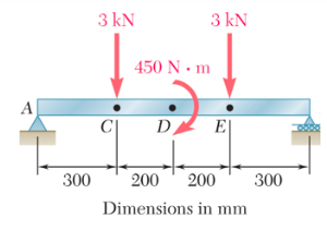
Draw the shear and bending moment diagrams for the beams shown
Homework Answers


*Subscript Clarification: VA indicates shear force at node A.
MA indicates moment at node A.
MCl indicates moment at just left side of node C.
MCr indicates moment at just right side of node C.
Thank you.
Add Answer to:
Draw the shear and bending moment diagrams for the beams
shown
3 KN 3 KN 450...
Draw the shear force and bending moment diagrams for the beams shown 5 kN 3 kN/m...
 Draw the shear force and bending moment diagrams for the beams
shown
5 kN 3 kN/m 3 m 1.5 m1.5mFig. 4 3 m
Draw the shear force and bending moment diagrams for the beams
shown
5 kN 3 kN/m 3 m 1.5 m1.5mFig. 4 3 m
Problem Determine the reactions and draw the shear and bending moment diagrams for the beams shown...
 Problem Determine the reactions and draw the shear and bending moment diagrams for the beams shown in Figs. P16.8-P16.14 by using the moment-distribution method 120 kN 120 kN 150 kN m--4 21 E 200 GPa 1- 500 (106 mm
4. Draw shear force & bending moment diagrams for the shown beams 30 kN 20 kN...
 4. Draw shear force & bending moment diagrams for the shown beams 30 kN 20 kN IO kN m DY E 15 kN 1 kip/ft 27 kip.ft 4.5 ft
6. For the beams and loading shown draw the shear and bending-moment diagrams and then find...
 6. For the beams and loading shown draw the shear and bending-moment diagrams and then find the maximum absolute values of the shear and bending moment. 2500 lb 60 KN 25 kN/m 500 lb /ft A c Di 5-3 ft--3--3-1-3ft Ć D -3 ft 3 ft — —3 ft 3 ft — Tam-kata2 122 m- 1 m
Question 3 For the following beam structure, draw the bending moment and shear force diagrams. Also,...
 Question 3 For the following beam structure, draw the bending moment and shear force diagrams. Also, identify the magnitude of maximum bending moment and shear force experienced by the beam. GS 1.8 kN 7 kN 1.8 KN 200 mm BE 200 mm 300 300
4. For the beam and loading shown, draw the shear force and bending moment diagrams and...
 4. For the beam and loading shown, draw the shear force and bending moment diagrams and determine the maximum bending and shear force and their locations. 20 KN 40 KN B D 250 mm |--2.5 m- 3m-4-2 m 80 mm 5. For the beam and loading shown, draw the shear force and bending moment diagrams and determine the maximum bending and shear force and their locations. 50 KN
Draw the shear and bending-moment diagrams for the beams and loadings shown (indicate position and magnitude...
 Draw the shear and bending-moment diagrams for the beams and
loadings shown (indicate position and magnitude of the maximum and
minimum shear and bending moment values in the diagrams):
P-2400 lb-(000 -400 bt 91- RB 24 ft
Draw the shear and bending-moment diagrams for the beams and
loadings shown (indicate position and magnitude of the maximum and
minimum shear and bending moment values in the diagrams):
P-2400 lb-(000 -400 bt 91- RB 24 ft
For the beams of problems 6.2-6.16, draw the shear force and bending moment diagrams and find...
 For the beams of problems 6.2-6.16, draw the shear force and
bending moment
diagrams and find the maximum shear force, maximum bending moment
and
point(s) of contraflexure (PCF).
7 kN 6 kN/m 4 kN/m B 2 m e C D E 24 kN 1,5m 7590.0.751 Figure 6.41
For the beams of problems 6.2-6.16, draw the shear force and
bending moment
diagrams and find the maximum shear force, maximum bending moment
and
point(s) of contraflexure (PCF).
7 kN 6 kN/m 4 kN/m B 2 m e C D E 24 kN 1,5m 7590.0.751 Figure 6.41
Draw shear force and bending moment diagrams for the beams shown below. Use matrix methods 25kN...
 Draw shear force and bending moment diagrams for the beams shown below. Use matrix methods 25kN 25 kN SkN/m | 1,1 C(Hinge) 1,1 | 1, 11 1,15
Determine the reactions and draw the shear and bending moment diagrams for the beams shown in...
 Determine the reactions and draw the shear and bending moment diagrams for the beams shown in Figs. P16.1-P16.5 by using the moment-distribution method. 2 k/ft 36 f24 ft El- constant E -29,000 ksi 1-1,530 in.4
 Draw the shear force and bending moment diagrams for the beams
shown
5 kN 3 kN/m 3 m 1.5 m1.5mFig. 4 3 m
Draw the shear force and bending moment diagrams for the beams
shown
5 kN 3 kN/m 3 m 1.5 m1.5mFig. 4 3 m
 Problem Determine the reactions and draw the shear and bending moment diagrams for the beams shown in Figs. P16.8-P16.14 by using the moment-distribution method 120 kN 120 kN 150 kN m--4 21 E 200 GPa 1- 500 (106 mm
 4. Draw shear force & bending moment diagrams for the shown beams 30 kN 20 kN IO kN m DY E 15 kN 1 kip/ft 27 kip.ft 4.5 ft
 6. For the beams and loading shown draw the shear and bending-moment diagrams and then find the maximum absolute values of the shear and bending moment. 2500 lb 60 KN 25 kN/m 500 lb /ft A c Di 5-3 ft--3--3-1-3ft Ć D -3 ft 3 ft — —3 ft 3 ft — Tam-kata2 122 m- 1 m
 Question 3 For the following beam structure, draw the bending moment and shear force diagrams. Also, identify the magnitude of maximum bending moment and shear force experienced by the beam. GS 1.8 kN 7 kN 1.8 KN 200 mm BE 200 mm 300 300
 4. For the beam and loading shown, draw the shear force and bending moment diagrams and determine the maximum bending and shear force and their locations. 20 KN 40 KN B D 250 mm |--2.5 m- 3m-4-2 m 80 mm 5. For the beam and loading shown, draw the shear force and bending moment diagrams and determine the maximum bending and shear force and their locations. 50 KN
 Draw the shear and bending-moment diagrams for the beams and
loadings shown (indicate position and magnitude of the maximum and
minimum shear and bending moment values in the diagrams):
P-2400 lb-(000 -400 bt 91- RB 24 ft
Draw the shear and bending-moment diagrams for the beams and
loadings shown (indicate position and magnitude of the maximum and
minimum shear and bending moment values in the diagrams):
P-2400 lb-(000 -400 bt 91- RB 24 ft
 For the beams of problems 6.2-6.16, draw the shear force and
bending moment
diagrams and find the maximum shear force, maximum bending moment
and
point(s) of contraflexure (PCF).
7 kN 6 kN/m 4 kN/m B 2 m e C D E 24 kN 1,5m 7590.0.751 Figure 6.41
For the beams of problems 6.2-6.16, draw the shear force and
bending moment
diagrams and find the maximum shear force, maximum bending moment
and
point(s) of contraflexure (PCF).
7 kN 6 kN/m 4 kN/m B 2 m e C D E 24 kN 1,5m 7590.0.751 Figure 6.41
 Draw shear force and bending moment diagrams for the beams shown below. Use matrix methods 25kN 25 kN SkN/m | 1,1 C(Hinge) 1,1 | 1, 11 1,15
 Determine the reactions and draw the shear and bending moment diagrams for the beams shown in Figs. P16.1-P16.5 by using the moment-distribution method. 2 k/ft 36 f24 ft El- constant E -29,000 ksi 1-1,530 in.4
Most questions answered within 3 hours.
-
You have a 825.3 mL sample of 2.754 M HA (Ka =
4.49⋅10−4). Calculate the pH...
asked 51 minutes ago -
The blues made its way into many kinds of music. Eric Clapton,
The Beatles, and Elvis...
asked 2 hours ago -
8. A wave in a string has a wave function given by: y (x, t) =...
asked 1 hour ago -
If you’re standing at the bottom of a hill and asked to evaluate
it while being...
asked 3 hours ago -
1. Which region has taken the lead in the world of
e-waste handling?
a) European Union...
asked 3 hours ago -
A 8.15- g bullet from a 9-mm pistol has a velocity of 366.0 m/s.
It strikes...
asked 5 hours ago -
The outstanding bonds of Alpha Extracts have a yield to maturity
of 7.4 percent and a...
asked 5 hours ago -
The Problem: The Case of the Harmonizing Vacations
Your CEO is exploring partnering with a European...
asked 6 hours ago -
A chemical equation is balanced by adding coefficients in front
of some formulas so that the...
asked 6 hours ago -
From the literature (reference your sources): What are the
lattice parameters of calcite and aragonite? Why...
asked 7 hours ago -
Your system is rejecting the question am asking which is
preceded by a case study. It...
asked 7 hours ago -
3. On January 2, 2000, Larry creates a trust with himself as
trustee. Larry as trustee...
asked 7 hours ago