![2. (8 marks] Design a sequential circuit specified by the state diagram in the figure below, using D flip-flops. A. (4 marks]](http://img.homeworklib.com/questions/2ee667c0-be7f-11eb-aafc-2fe27e414092.png?x-oss-process=image/resize,w_560)
Homework Answers

Add Answer to:
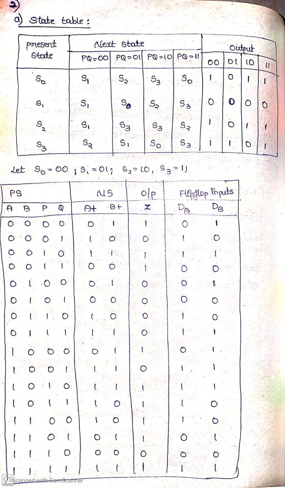
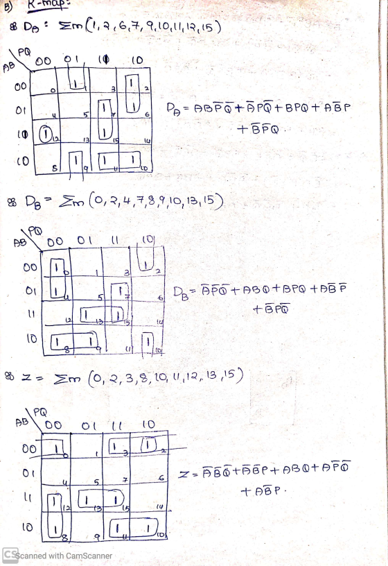
2. (8 marks] Design a sequential circuit specified by the state diagram in the figure below,...
3. A sequential circuit has 2 JK flip-flops A and B and one input x. The...
 3. A sequential circuit has 2 JK flip-flops A and B and one input x. The circuit is described by the following flip-flop input equations: (a) Derive the state equations A(t1) and B(t +1) by substituting the input equations for the J and K variables (b) Draw the state diagram of the circuit (c) Design an equivalent circuit using D flip flops, i.e. a sequential circuit that uses D flip flops to implement the state diagram you obtained in part...
A combination circuit is specified by the following Boolean functions listed below. h(a, b, c) = b,c' + a'c Implement the circuit with a 3x8 decoder. Provide truth table and drawing the l...
 A combination circuit is specified by the following Boolean functions listed below. h(a, b, c) = b,c' + a'c Implement the circuit with a 3x8 decoder. Provide truth table and drawing the logic/circuit diagram. Use the block diagram for the decoder provided in Figure A4 in supplements. Please label the inputs and outputs clearly. Note: use single 3x8 decoder Question 2 (15 points] A priority encoder is an encoder circuit that includes the Truth Table of a priority function. The...
Design a synchronous sequential counter circuit that has the state diagram shown in figure 1. Use...
 Design a synchronous sequential counter circuit that has the state diagram shown in figure 1. Use both D-type and T-type Flip Flops in your design. Show all your work in details. Extra credit will be given for implementation using other types of Flip Flops 3 4 Figure 1 Deliverables: 1. State Transition Table 2. K-Maps 3. Logical Expressions (Minimal Form) 4. Schematic Diagrams of the two designs 5. Verification steps for both designs.
HW#4-SYNCHRONOUS SEQUENTIAL CIRCUIT DESIGN Given the following state diagram, obtain the corresponding synchronous sequential circuit with...
 HW#4-SYNCHRONOUS SEQUENTIAL CIRCUIT DESIGN Given the following state diagram, obtain the corresponding synchronous sequential circuit with D flip-flops. Draw this circuit. (Use x as an input, and z as an output). 50 points] 1) 1/0 0/0 1/0
ECE 260 HW 7 NAME 1. A sequential circuit has two JK flip-flops A and B,...
 ECE 260 HW 7 NAME 1. A sequential circuit has two JK flip-flops A and B, two inputs X and Y, and one output Z. The flip-flop input equations and circuit output equation are: (a) Draw the sequential circuit (b) Derive the state equations for Q and Q (c) Construct the state/output table (d) Draw the state diagram Note, for JK flip-flop: Q1O+KQ Design a sequential circuit with two JK flip-flops A and B and two inputs E and F....
(25 pts) 5. The state diagram of a synchronous sequential circuit is shown below. X is...
 (25 pts) 5. The state diagram of a synchronous sequential circuit is shown below. X is an external input and Z is the output. (a) Design the circuit using D flip-flops. (b) Draw the logic diagram. A/0 B/0 Clas Сл D/0
1. Given the state diagram shown below for a two-state synchronous sequential Mealy circuit with input....
 1. Given the state diagram shown below for a two-state synchronous sequential Mealy circuit with input. and output z, realize the circuit using D flip-flops. Your answer must include the state transition,excita- tion, and output tables, the excitation equation(s), and a labeled circuit diagram 1/0 2. Given the state diagram in Problem 1, realize the circuit using JK flip-flops. Your answer must include the state transition, excitation, and output tables, the excitation equation(s), and a labeled circuit diagram. 3. Given...
03: 6 marks) Sequential circuit that has two flip-flops A and B and one input x...
 03: 6 marks) Sequential circuit that has two flip-flops A and B and one input x and a constant 'l'. It consists of a combinatorial logic connected to the JK flip-flops, as shown in Figure below. a. (2 marks) Derive the next state and output equations. b. (2 marks) Derive the state table of the sequential circuit. c. (2 marks) Draw the corresponding state diagram. K ā
Draw a Moore-type state diagram and design a synchronous sequential circuit using D flip flops for...
Draw a Moore-type state diagram and design a synchronous sequential circuit using D flip flops for a 1-input/1-output "sequence detector" for the sequence 110 (be sure to recognize overlapping sequences). Draw the final circuit.
Draw a Moore-type state diagram and design a synchronous sequential circuit using D flip flops for...
Draw a Moore-type state diagram and design a synchronous sequential circuit using D flip flops for a 1-input/1-output "sequence detector" for the sequence 1001 (be sure to recognize overlapping sequences). Draw the final circuit.
 3. A sequential circuit has 2 JK flip-flops A and B and one input x. The circuit is described by the following flip-flop input equations: (a) Derive the state equations A(t1) and B(t +1) by substituting the input equations for the J and K variables (b) Draw the state diagram of the circuit (c) Design an equivalent circuit using D flip flops, i.e. a sequential circuit that uses D flip flops to implement the state diagram you obtained in part...
 A combination circuit is specified by the following Boolean functions listed below. h(a, b, c) = b,c' + a'c Implement the circuit with a 3x8 decoder. Provide truth table and drawing the logic/circuit diagram. Use the block diagram for the decoder provided in Figure A4 in supplements. Please label the inputs and outputs clearly. Note: use single 3x8 decoder Question 2 (15 points] A priority encoder is an encoder circuit that includes the Truth Table of a priority function. The...
 Design a synchronous sequential counter circuit that has the state diagram shown in figure 1. Use both D-type and T-type Flip Flops in your design. Show all your work in details. Extra credit will be given for implementation using other types of Flip Flops 3 4 Figure 1 Deliverables: 1. State Transition Table 2. K-Maps 3. Logical Expressions (Minimal Form) 4. Schematic Diagrams of the two designs 5. Verification steps for both designs.
 HW#4-SYNCHRONOUS SEQUENTIAL CIRCUIT DESIGN Given the following state diagram, obtain the corresponding synchronous sequential circuit with D flip-flops. Draw this circuit. (Use x as an input, and z as an output). 50 points] 1) 1/0 0/0 1/0
 ECE 260 HW 7 NAME 1. A sequential circuit has two JK flip-flops A and B, two inputs X and Y, and one output Z. The flip-flop input equations and circuit output equation are: (a) Draw the sequential circuit (b) Derive the state equations for Q and Q (c) Construct the state/output table (d) Draw the state diagram Note, for JK flip-flop: Q1O+KQ Design a sequential circuit with two JK flip-flops A and B and two inputs E and F....
 (25 pts) 5. The state diagram of a synchronous sequential circuit is shown below. X is an external input and Z is the output. (a) Design the circuit using D flip-flops. (b) Draw the logic diagram. A/0 B/0 Clas Сл D/0
 1. Given the state diagram shown below for a two-state synchronous sequential Mealy circuit with input. and output z, realize the circuit using D flip-flops. Your answer must include the state transition,excita- tion, and output tables, the excitation equation(s), and a labeled circuit diagram 1/0 2. Given the state diagram in Problem 1, realize the circuit using JK flip-flops. Your answer must include the state transition, excitation, and output tables, the excitation equation(s), and a labeled circuit diagram. 3. Given...
 03: 6 marks) Sequential circuit that has two flip-flops A and B and one input x and a constant 'l'. It consists of a combinatorial logic connected to the JK flip-flops, as shown in Figure below. a. (2 marks) Derive the next state and output equations. b. (2 marks) Derive the state table of the sequential circuit. c. (2 marks) Draw the corresponding state diagram. K ā
Most questions answered within 3 hours.
-
Part 1. Primitive Types, Sorting, Recursion for
Homework.java
a) Implement the static method initializeArray that receives...
asked 26 minutes ago -
Using C++, build a sorter that can rank a sequence of numbers in
a descending order....
asked 23 minutes ago -
Derive ground state term symbols. Use notation 2S(1/2) for state
2S1/2
a) d5
b) f3
c)...
asked 46 minutes ago -
A sample of size 31 will be drawn from a population with mean 39
and standard...
asked 1 hour ago -
What is the effect on the P-value when a test is changed from a
two-tailed hypothesis...
asked 1 hour ago -
I wish to estimate µ, the mean of a population. After I collect
and an-
alyze...
asked 1 hour ago -
At a local university, you poll a group of 115 students and find
that 37 of...
asked 1 hour ago -
Gladstone company tracks the number of units purchased and sold
throughout each accounting period but applies...
asked 1 hour ago -
When determining if a molecule's configuration is E or Z, what
determines the higher priority groups?
asked 1 hour ago -
13. What is the amount
of conversion cost transferred to finished goods? (Round
your intermediate calculations...
asked 1 hour ago -
Sulfuric Acid is a "strong" acid, but only releases a single
proton when it dissolves. What...
asked 1 hour ago -
The
second floor of a house is 6 m above the street level. How much
work...
asked 1 hour ago