
Homework Answers
Lets analyze the problem with Moment distribution method
Point load in member AB,P=10kN
UDL in member BC, w=12kN/m
LAB=4 m, LBC=4 m
Fixed end moments
Member AB
FEMAB= -PL/8= -5 kNm
FEMBA= + PL/8= +5 kNm
Member BC
FEMBC= -wL2/12= -12*16/12= -16 kNm
FEMCB= +wL2/12= +12*16/12= +16 kNm
|
Joint |
Member |
Stiffness |
Total Stiffness |
DF |
|
B |
BA |
4EI/4 |
EI |
0.5 |
|
BC |
4EI/4 |
EI |
0.5 |
|
A |
B |
C |
|||
|
0.5 |
0.5 |
0 |
|||
|
FEM |
-5 |
5 |
-16 |
16 |
|
|
Balancing correction |
5.5 |
5.5 |
|||
|
Carry over |
2.75 |
2.75 |
|||
|
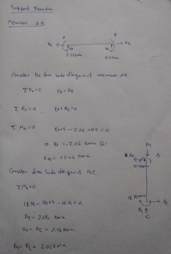
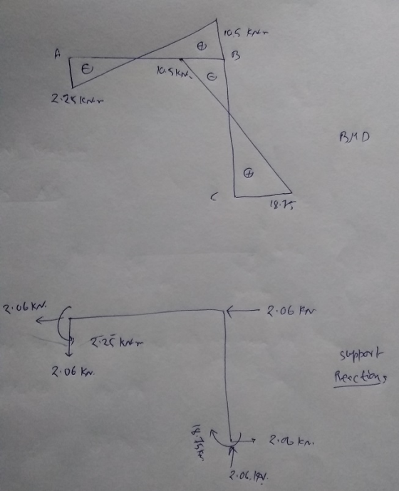
Final End moments |
-2.25 |
10.5 |
-10.5 |
18.75 |
Add Answer to:
The frame shown below is fixed at A and C, and is supported by a roller...
The rigid frame shown below is supported by Pin A and Roller C.
 The rigid frame shown below is supported by Pin A and Roller C. [Point B is a rigid joint.] The frame supports a uniformly distributed load of 20 kN/m (downward) in Region BC, and a 250 kN point load (downward) located halfway between Pin A and rigid joint B. The modulus of elasticity of the entire frame is E = 200 GPa and the moment of inertia is I = 500 x 106 mm4. Determine the rotation (slope) at Joint...
The frame shown is fixed supported at A and is supported by elastic springs at C in the horizonta...
 The frame shown is fixed supported at A and is supported by
elastic springs at C in the horizontal and vertical directions. The
frame has constant EI = 50,000 kN-m2. The stiffness of the
horizontal spring is kh = 10,000 kN/m and that of the vertical
spring is kv = 15,000 kN/m.
(a) Take the moment at A and the horizontal spring at C as the
redundant reactions and write
the compatibility equations in matrix form.
(b) Solve the equations...
The frame shown is fixed supported at A and is supported by
elastic springs at C in the horizontal and vertical directions. The
frame has constant EI = 50,000 kN-m2. The stiffness of the
horizontal spring is kh = 10,000 kN/m and that of the vertical
spring is kv = 15,000 kN/m.
(a) Take the moment at A and the horizontal spring at C as the
redundant reactions and write
the compatibility equations in matrix form.
(b) Solve the equations...
16-5. Determine the structure stiffness matrix K for the 200 GPa, are fixed. Take E and frame. Assume 1-300 105) mm,A 1...
 16-5. Determine the structure stiffness matrix K for the 200 GPa, are fixed. Take E and frame. Assume 1-300 105) mm,A 10(10) mm2 for each member. 16-6. Determine the support reactions at the fixed supports D and . Take E-200 GPa,1 300 (10) mm, A 10(10) mm2 for each member. 12 kN/m 2 m 4 m 12 2 m Probs. 16-5/6
16-5. Determine the structure stiffness matrix K for the 200 GPa, are fixed. Take E and frame. Assume 1-300...
16-5. Determine the structure stiffness matrix K for the 200 GPa, are fixed. Take E and frame. Assume 1-300 105) mm,A 10(10) mm2 for each member. 16-6. Determine the support reactions at the fixed supports D and . Take E-200 GPa,1 300 (10) mm, A 10(10) mm2 for each member. 12 kN/m 2 m 4 m 12 2 m Probs. 16-5/6
16-5. Determine the structure stiffness matrix K for the 200 GPa, are fixed. Take E and frame. Assume 1-300...
QUESTION 1 [25 marks A frame loaded with a uniformly distributed load at Member AB and...
 QUESTION 1 [25 marks A frame loaded with a uniformly distributed load at Member AB and point load at Member BC and joint B. It has pinned supports A and C, while joint B is fixed connected, as can be seen in Figure 1. Take E-200 GPa. a) Using the slope-deflection method, calculate the moments and illustrate the bending moment diagram. [15 marks) b) Then calculate the shear forces and sketch the shear force diagram. [10 marks) 22 KN 10...
SAN4701 OCT/NOV 2017 QUESTION 1 The beam shown in Figure 1 is fixed at support A and support C, support B is a roller s...
 SAN4701 OCT/NOV 2017 QUESTION 1 The beam shown in Figure 1 is fixed at support A and support C, support B is a roller support. Use the stiffness matrix method to determine the. Member stiffness matrix 11 1.2 Structure and load matrix (10) 13 Displacement matrix Reactions at the support 14 15. Moments at the fixed supports El is constant along the length of the beam 18 kN 10 kN 20 m 10 m 1 15 m15 m Figure 1...
The simply supported beam shown in Figure 1 is pin-supported at A and roller-supported at D....
 The simply supported beam shown in Figure 1 is pin-supported at A and roller-supported at D. la) Replace the distributed loads in Figure 1 by an equivalent resultant force and locate its location with respect to A. {2 + 3 marks 1b) Calculate the reactions at supports A and D. {2 marks 1c) Calculate the shear force and bending moment at point C. {4 marks) 15 kN/m 6 kN/m D B q 3.0 m 3.0 m 3.0 m Figure 1
QUESTION 2 Beam ABCD is 8 m in length and is pin-supported at A and roller-supported...
 QUESTION 2 Beam ABCD is 8 m in length and is pin-supported at A and roller-supported at C as shown in Figure Q2. A counter-clockwise concentrated moment acts about the support A. A uniformly-distributed load acts on span BC and a vertical concentrated load acts at the free end D a) Determine the reactions at supports A and C. 4 marks) b) Obtain the shear force and the bending moment functions (in terms of x) for each segment along the...
The beam ABC is supported at A with a guided support (fixed with roller) and hinge...
 The beam ABC is supported at A with a guided support (fixed with roller) and hinge at B has rectangular cross section and supports concentrated loads P both ends A and C as shown in the figure. The span length from A to B is L, and the length of the overhang is 1/2. Point D is located midway between the supports at a distance d from the top face of the beam Knowing that the maximum tensile stress (principal...
tatically determinate or indeterminate frame analysis by the stiffness method (45 marks) a) Determine the stiffine...
 tatically determinate or indeterminate frame analysis by the stiffness method (45 marks) a) Determine the stiffiness matrix of the frame of problems 16.5 and 16.6 (p. 619). Indicate the degrees-of freedom in all the stiffness matrices. b) D Q4. S (10 marks) etermine all the displacement components at node 2 and all the reactions including the reactions at node 2. Show all calculations. c) (18 marks) of the frame on the compression side showing all the salient values (5 marks)...
The beam ABC is supported at A with a guided support (fixed with roller) and hinge...
 The beam ABC is supported at A with a guided support (fixed with roller) and hinge at B has rectangular cross section and supports concentrated loads P both ends A and C as shown in the figure. The span length from A to Bis L, and the length of the overhang is 1/2. Point D is located midway between the supports at a distance d from the top face of the beam Knowing that the maximum tensile stress (principal stress)...
 The frame shown is fixed supported at A and is supported by
elastic springs at C in the horizontal and vertical directions. The
frame has constant EI = 50,000 kN-m2. The stiffness of the
horizontal spring is kh = 10,000 kN/m and that of the vertical
spring is kv = 15,000 kN/m.
(a) Take the moment at A and the horizontal spring at C as the
redundant reactions and write
the compatibility equations in matrix form.
(b) Solve the equations...
The frame shown is fixed supported at A and is supported by
elastic springs at C in the horizontal and vertical directions. The
frame has constant EI = 50,000 kN-m2. The stiffness of the
horizontal spring is kh = 10,000 kN/m and that of the vertical
spring is kv = 15,000 kN/m.
(a) Take the moment at A and the horizontal spring at C as the
redundant reactions and write
the compatibility equations in matrix form.
(b) Solve the equations...
 16-5. Determine the structure stiffness matrix K for the 200 GPa, are fixed. Take E and frame. Assume 1-300 105) mm,A 10(10) mm2 for each member. 16-6. Determine the support reactions at the fixed supports D and . Take E-200 GPa,1 300 (10) mm, A 10(10) mm2 for each member. 12 kN/m 2 m 4 m 12 2 m Probs. 16-5/6
16-5. Determine the structure stiffness matrix K for the 200 GPa, are fixed. Take E and frame. Assume 1-300...
16-5. Determine the structure stiffness matrix K for the 200 GPa, are fixed. Take E and frame. Assume 1-300 105) mm,A 10(10) mm2 for each member. 16-6. Determine the support reactions at the fixed supports D and . Take E-200 GPa,1 300 (10) mm, A 10(10) mm2 for each member. 12 kN/m 2 m 4 m 12 2 m Probs. 16-5/6
16-5. Determine the structure stiffness matrix K for the 200 GPa, are fixed. Take E and frame. Assume 1-300...
 QUESTION 1 [25 marks A frame loaded with a uniformly distributed load at Member AB and point load at Member BC and joint B. It has pinned supports A and C, while joint B is fixed connected, as can be seen in Figure 1. Take E-200 GPa. a) Using the slope-deflection method, calculate the moments and illustrate the bending moment diagram. [15 marks) b) Then calculate the shear forces and sketch the shear force diagram. [10 marks) 22 KN 10...
 SAN4701 OCT/NOV 2017 QUESTION 1 The beam shown in Figure 1 is fixed at support A and support C, support B is a roller support. Use the stiffness matrix method to determine the. Member stiffness matrix 11 1.2 Structure and load matrix (10) 13 Displacement matrix Reactions at the support 14 15. Moments at the fixed supports El is constant along the length of the beam 18 kN 10 kN 20 m 10 m 1 15 m15 m Figure 1...
 The simply supported beam shown in Figure 1 is pin-supported at A and roller-supported at D. la) Replace the distributed loads in Figure 1 by an equivalent resultant force and locate its location with respect to A. {2 + 3 marks 1b) Calculate the reactions at supports A and D. {2 marks 1c) Calculate the shear force and bending moment at point C. {4 marks) 15 kN/m 6 kN/m D B q 3.0 m 3.0 m 3.0 m Figure 1
 QUESTION 2 Beam ABCD is 8 m in length and is pin-supported at A and roller-supported at C as shown in Figure Q2. A counter-clockwise concentrated moment acts about the support A. A uniformly-distributed load acts on span BC and a vertical concentrated load acts at the free end D a) Determine the reactions at supports A and C. 4 marks) b) Obtain the shear force and the bending moment functions (in terms of x) for each segment along the...
 The beam ABC is supported at A with a guided support (fixed with roller) and hinge at B has rectangular cross section and supports concentrated loads P both ends A and C as shown in the figure. The span length from A to B is L, and the length of the overhang is 1/2. Point D is located midway between the supports at a distance d from the top face of the beam Knowing that the maximum tensile stress (principal...
 tatically determinate or indeterminate frame analysis by the stiffness method (45 marks) a) Determine the stiffiness matrix of the frame of problems 16.5 and 16.6 (p. 619). Indicate the degrees-of freedom in all the stiffness matrices. b) D Q4. S (10 marks) etermine all the displacement components at node 2 and all the reactions including the reactions at node 2. Show all calculations. c) (18 marks) of the frame on the compression side showing all the salient values (5 marks)...
 The beam ABC is supported at A with a guided support (fixed with roller) and hinge at B has rectangular cross section and supports concentrated loads P both ends A and C as shown in the figure. The span length from A to Bis L, and the length of the overhang is 1/2. Point D is located midway between the supports at a distance d from the top face of the beam Knowing that the maximum tensile stress (principal stress)...
Most questions answered within 3 hours.
-
Water flowing uniformly in a rectangular open channel has
manning value of 0.017, bottom slope of...
asked 17 minutes ago -
Nature Conservancy's leader abruptly steps
down.
One morning in October 2007, Steven. J. McCormick the president...
asked 22 minutes ago -
I asked a question similar to this one, which was answered
perfectly. Another practice problem is...
asked 31 minutes ago -
Rachel is studying cholesterol synthesis in mice. Some mice
had a mutation in their sterol regulatory...
asked 27 minutes ago -
Railco sells to its customers on account with terms of 2% / 5
/net 15. Ronco...
asked 35 minutes ago -
Refer to the following lease amortization schedule. The 10
payments are made annually starting with the...
asked 50 minutes ago -
Explain how God fits into Aquinas' theory of happiness.
asked 57 minutes ago -
1.1 With aid of diagrams and suitable examples discuss
the economic effects of price controls.
1.2...
asked 1 hour ago -
When the nuclide polonium-214 undergoes alpha
decay:
The name of the product nuclide is .
The...
asked 1 hour ago -
Q. The market demand function is D(Pd) = 160 - 2Pd and the
market supply function...
asked 1 hour ago -
An unknown alcohol is analyzed by freezing point depression. The
unknown is either methanol (CH3OH), ethanol...
asked 1 hour ago -
As a person inhales, air moves down the windpipe (bronchus),
through a constriction where the air...
asked 1 hour ago