
Homework Answers
Add Answer to:
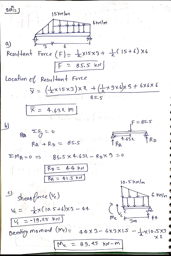
The simply supported beam shown in Figure 1 is pin-supported at A and roller-supported at D....
QUESTION 2 Beam ABCD is 8 m in length and is pin-supported at A and roller-supported...
 QUESTION 2 Beam ABCD is 8 m in length and is pin-supported at A and roller-supported at C as shown in Figure Q2. A counter-clockwise concentrated moment acts about the support A. A uniformly-distributed load acts on span BC and a vertical concentrated load acts at the free end D a) Determine the reactions at supports A and C. 4 marks) b) Obtain the shear force and the bending moment functions (in terms of x) for each segment along the...
Q2(c) Figure Q1(c) shows a simply supported beam ABCD loaded as shown. The beam is pin-supported...
 Q2(c) Figure Q1(c) shows a simply supported beam ABCD loaded as shown. The beam is pin-supported at D, while point B is roller-supported. Determine the support reactions. b) For span BC (2<x< 4) write down the x-dependent equation for moment. x should be measured from cnd A. Plot the shear force diagram and the bending moment diagram for the beam. Show all important values of the diagrams. d) Plot the deflected shape of the beam. c) 50KN 40kN/m 25kNm 20kN/m...
QUESTION 1 [15] For the simply supported beam subjected to the loading shown in the figure,...
 QUESTION 1 [15] For the simply supported beam subjected to the loading shown in the figure, a) Derive equations for the shear force V and the bending moment M for any location in the beam. (Place the origin at point A.) b) Report the maximum positive bending moment, the maximum negative bending moment, and their respective locations. 36 KN 180 KN-m X B C D 4 m 5 m 3 m Figure 1
The beam AC is supported by a smooth pin at A and a roller at B...
 The beam AC is supported by a smooth pin at A and a roller at B
as shown in the figure below.
a. Sketch the free-body diagram of the beam and use it to
determine the support reaction components at A and B.
b. Draw the shear and moment diagrams for the beam.
6. The beam AC is supported by a smooth pin at A and a roller at B as shown in the figure below. 6 kN 12 kN/m...
The beam AC is supported by a smooth pin at A and a roller at B
as shown in the figure below.
a. Sketch the free-body diagram of the beam and use it to
determine the support reaction components at A and B.
b. Draw the shear and moment diagrams for the beam.
6. The beam AC is supported by a smooth pin at A and a roller at B as shown in the figure below. 6 kN 12 kN/m...
Question 2: A simply supported beam under loading as shown in Figure 1: 1. Draw the influence lines of the bending moment and shear force at point C (L/4) Using the influence lines to determine t...
 Question 2: A simply supported beam under loading as shown in Figure 1: 1. Draw the influence lines of the bending moment and shear force at point C (L/4) Using the influence lines to determine the bending moment and shear force at section C due to the loading as shown in the figure. 2. 3. There is a distributed live load (w#2.5kN/m) which can vary the location along the beam. Determine the location of the live loads which create the...
The simply supported beam is supported by pin support A and roller support C. It is...
 The simply supported beam is supported by pin support A and roller support C. It is subjected to a uniform distributed load w, and a couple moment M. If wand Min the image are positive real numbers, select the correct shear force and bending moment diagram: w M B -5 m 5 m .X Internal Shear Force V(x) Funciton Internal Bending Moment M(x) Funciton 40 30 20 10 V(x) Mix) 0 -10 -20 6 -30 -40 0 5 TO 5...
The beam is loaded as shown in the diagram below. The beam is uniformly loaded at...
 The beam is loaded as shown in the diagram below. The beam is uniformly loaded at 3 kN/m for the length of 4 m from B. The beam also has two point loads, 4 KN at 2 m from A and 3 KN at 3 m from B. 2 KN 3 KN 3KN/m A 2 m 2 m 11 m 3 m Fig. Q2 Draw a shear force and bending moment diagram. Also determine the location of maximum bending moment...
1) The uniform beam shown is supported by a pin at A and a light rope...
 1) The uniform beam shown is supported by a pin at A and a light rope at B. A 1,000 lb weight is supported at C. Determine the normal force, shear force, and bending moment at point P. (15 p.) 30 3 А 2) The uniform beam shown is supported by a pin at and a roller at B. Using the analytical method (i.e., sections), construct the shear and moment diagrams. Write your equations V(x) and Mix) for each section...
Consider the simply supported beam and loaded as shown in the M figure. Perform the following:...
 Consider the simply supported beam and loaded as shown in the M figure. Perform the following: 1. Determine the support reactions. 2. Plot SFD and BMD 3. if L=9 m, the beam will fail when the maximum shear force is Vmax= 5 kN or the maximum bending moment is Mmax=22 kN.m. Determine the largest couple moment Mo the beam will support.
The beam shown (Figure 1) is supported by a pin at A and a cable at...
 The beam shown (Figure 1) is
supported by a pin at A and a cable at B. Two
loads P = 13 kN are applied straight down from the
centerline of the bottom face. Determine the state of stress at the
point shown (Figure 2) in a section 2 m from the wall. The
dimensions are w = 5.2 cm , h = 10.5 cm ,
L = 0.8 m , a = 1.5 cm , and b = 4...
The beam shown (Figure 1) is
supported by a pin at A and a cable at B. Two
loads P = 13 kN are applied straight down from the
centerline of the bottom face. Determine the state of stress at the
point shown (Figure 2) in a section 2 m from the wall. The
dimensions are w = 5.2 cm , h = 10.5 cm ,
L = 0.8 m , a = 1.5 cm , and b = 4...
 QUESTION 2 Beam ABCD is 8 m in length and is pin-supported at A and roller-supported at C as shown in Figure Q2. A counter-clockwise concentrated moment acts about the support A. A uniformly-distributed load acts on span BC and a vertical concentrated load acts at the free end D a) Determine the reactions at supports A and C. 4 marks) b) Obtain the shear force and the bending moment functions (in terms of x) for each segment along the...
 Q2(c) Figure Q1(c) shows a simply supported beam ABCD loaded as shown. The beam is pin-supported at D, while point B is roller-supported. Determine the support reactions. b) For span BC (2<x< 4) write down the x-dependent equation for moment. x should be measured from cnd A. Plot the shear force diagram and the bending moment diagram for the beam. Show all important values of the diagrams. d) Plot the deflected shape of the beam. c) 50KN 40kN/m 25kNm 20kN/m...
 QUESTION 1 [15] For the simply supported beam subjected to the loading shown in the figure, a) Derive equations for the shear force V and the bending moment M for any location in the beam. (Place the origin at point A.) b) Report the maximum positive bending moment, the maximum negative bending moment, and their respective locations. 36 KN 180 KN-m X B C D 4 m 5 m 3 m Figure 1
 The beam AC is supported by a smooth pin at A and a roller at B
as shown in the figure below.
a. Sketch the free-body diagram of the beam and use it to
determine the support reaction components at A and B.
b. Draw the shear and moment diagrams for the beam.
6. The beam AC is supported by a smooth pin at A and a roller at B as shown in the figure below. 6 kN 12 kN/m...
The beam AC is supported by a smooth pin at A and a roller at B
as shown in the figure below.
a. Sketch the free-body diagram of the beam and use it to
determine the support reaction components at A and B.
b. Draw the shear and moment diagrams for the beam.
6. The beam AC is supported by a smooth pin at A and a roller at B as shown in the figure below. 6 kN 12 kN/m...
 Question 2: A simply supported beam under loading as shown in Figure 1: 1. Draw the influence lines of the bending moment and shear force at point C (L/4) Using the influence lines to determine the bending moment and shear force at section C due to the loading as shown in the figure. 2. 3. There is a distributed live load (w#2.5kN/m) which can vary the location along the beam. Determine the location of the live loads which create the...
 The simply supported beam is supported by pin support A and roller support C. It is subjected to a uniform distributed load w, and a couple moment M. If wand Min the image are positive real numbers, select the correct shear force and bending moment diagram: w M B -5 m 5 m .X Internal Shear Force V(x) Funciton Internal Bending Moment M(x) Funciton 40 30 20 10 V(x) Mix) 0 -10 -20 6 -30 -40 0 5 TO 5...
 The beam is loaded as shown in the diagram below. The beam is uniformly loaded at 3 kN/m for the length of 4 m from B. The beam also has two point loads, 4 KN at 2 m from A and 3 KN at 3 m from B. 2 KN 3 KN 3KN/m A 2 m 2 m 11 m 3 m Fig. Q2 Draw a shear force and bending moment diagram. Also determine the location of maximum bending moment...
 1) The uniform beam shown is supported by a pin at A and a light rope at B. A 1,000 lb weight is supported at C. Determine the normal force, shear force, and bending moment at point P. (15 p.) 30 3 А 2) The uniform beam shown is supported by a pin at and a roller at B. Using the analytical method (i.e., sections), construct the shear and moment diagrams. Write your equations V(x) and Mix) for each section...
 Consider the simply supported beam and loaded as shown in the M figure. Perform the following: 1. Determine the support reactions. 2. Plot SFD and BMD 3. if L=9 m, the beam will fail when the maximum shear force is Vmax= 5 kN or the maximum bending moment is Mmax=22 kN.m. Determine the largest couple moment Mo the beam will support.
 The beam shown (Figure 1) is
supported by a pin at A and a cable at B. Two
loads P = 13 kN are applied straight down from the
centerline of the bottom face. Determine the state of stress at the
point shown (Figure 2) in a section 2 m from the wall. The
dimensions are w = 5.2 cm , h = 10.5 cm ,
L = 0.8 m , a = 1.5 cm , and b = 4...
The beam shown (Figure 1) is
supported by a pin at A and a cable at B. Two
loads P = 13 kN are applied straight down from the
centerline of the bottom face. Determine the state of stress at the
point shown (Figure 2) in a section 2 m from the wall. The
dimensions are w = 5.2 cm , h = 10.5 cm ,
L = 0.8 m , a = 1.5 cm , and b = 4...
Most questions answered within 3 hours.
-
(Expected rate of return and risk) Carter Inc. is evaluating a
security. Calculate the investment’s expected...
asked 2 hours ago -
What specific indicators can point to lack of progress for
African Americans in American society?
asked 3 hours ago -
1-The Electrons in a beam are moving at 2.7×10⁸ m/s in an
electric field of 15000...
asked 3 hours ago -
A gas tank is a vertical cylinder. It has a radius of 1m, a
height of...
asked 4 hours ago -
Accent Software faces the following conditions. All of these
support Accent’s use of a market-penetration pricing...
asked 5 hours ago -
A mathematically inclined friend emails you the following
instructions: "Meet me in the cafeteria the first...
asked 5 hours ago -
A monopoly sells in two countries . The demand curves in the two
countries are p1...
asked 6 hours ago -
A .15kg rubber ball is bounced off a wall. Before hitting the
wall, the ball moves...
asked 6 hours ago -
A manufacturing company preparing to build a new plant is
considering three potential locations for it....
asked 6 hours ago -
B. If compound Y has approximately the same values of solubility
in toluene as compound X,...
asked 7 hours ago -
Oscar Inc. has inventory in Japan valued at 39,051,000 Yen one
year ago. One year ago...
asked 7 hours ago -
If Canada suffered from "fundamental disequilibrium," and its
government choose not to devalue its currency, a...
asked 7 hours ago