1.Sketch the physical system, showing measurement points and control loops.
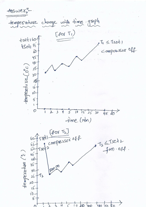
2.Sketch a graph of the temperature change with time, showing when the fan, compressor, and heater switch on or off.
Do this for T1 and T2.temperature change on y-axis with time on x-axis

Homework Answers

Add Answer to:
1.Sketch the physical system, showing measurement points
and control loops.
2.Sketch a graph of the temperature...
fOne question but divided into sub connected questions * Question Completion Status: QUESTION 1 20 points...
 fOne question but divided into sub connected
questions
* Question Completion Status: QUESTION 1 20 points Save Ans The heat-pump system shown is designed to provide water-heating and space-cooling. The system includes a heat exchanger to subcool the R134a refrigerant at the outlet of the water heater while heating the refrigerant at the outlet of the evaporator. Given the following data, determine the enthalpy at each station, 1 through 6, using the R134a property tables (click here). Type your answers...
fOne question but divided into sub connected
questions
* Question Completion Status: QUESTION 1 20 points Save Ans The heat-pump system shown is designed to provide water-heating and space-cooling. The system includes a heat exchanger to subcool the R134a refrigerant at the outlet of the water heater while heating the refrigerant at the outlet of the evaporator. Given the following data, determine the enthalpy at each station, 1 through 6, using the R134a property tables (click here). Type your answers...
EXPERIMENT 2 Table 1: Table of Measurements FREE CONVECTION Heat Transfer Surface at Power = 90...
 EXPERIMENT 2 Table 1: Table of Measurements FREE CONVECTION Heat Transfer Surface at Power = 90 W AIM T2 T1 Difference Ts - TIN (°C) . To compare the time taken for each surface to reach a given temperature for a fixed input power Time (seconds) Surface Ts (°C) Duct Inlet (ambient) TIN (°C) Flat Finned Pinned Flat Finned Pinned Flat Finned Pinned To understand the different thermal inertia characteristics of each heat surface for free convection 0 39.8 29.7...
(might be 1 or 2, MCQ questions were having images given with them, which we couldn't...
(might be 1 or 2, MCQ questions were having images given with them, which we couldn't insert, so ignore those questions if you cannot answer, sorry for inconveinience created, i tried to delete them but might be couldn't done all) 3) Single phase induction motors work because: a) The oscillating magnetic field can induce starting torque in a rotor. b) The oscillating magnetic field can induce running torque in a rotor. c) A capacitance or inductance can create the phase...
 fOne question but divided into sub connected
questions
* Question Completion Status: QUESTION 1 20 points Save Ans The heat-pump system shown is designed to provide water-heating and space-cooling. The system includes a heat exchanger to subcool the R134a refrigerant at the outlet of the water heater while heating the refrigerant at the outlet of the evaporator. Given the following data, determine the enthalpy at each station, 1 through 6, using the R134a property tables (click here). Type your answers...
fOne question but divided into sub connected
questions
* Question Completion Status: QUESTION 1 20 points Save Ans The heat-pump system shown is designed to provide water-heating and space-cooling. The system includes a heat exchanger to subcool the R134a refrigerant at the outlet of the water heater while heating the refrigerant at the outlet of the evaporator. Given the following data, determine the enthalpy at each station, 1 through 6, using the R134a property tables (click here). Type your answers...
 EXPERIMENT 2 Table 1: Table of Measurements FREE CONVECTION Heat Transfer Surface at Power = 90 W AIM T2 T1 Difference Ts - TIN (°C) . To compare the time taken for each surface to reach a given temperature for a fixed input power Time (seconds) Surface Ts (°C) Duct Inlet (ambient) TIN (°C) Flat Finned Pinned Flat Finned Pinned Flat Finned Pinned To understand the different thermal inertia characteristics of each heat surface for free convection 0 39.8 29.7...
Most questions answered within 3 hours.
-
Other decisions about scientific claims can have a much broader
impact.ENERGYarrow-10x10.png, environment, health, security - all...
asked 44 minutes ago -
I need to write a research paper and work cited about this
topic: The United States...
asked 1 hour ago -
Hello! I was wondering if I could have some help?
If the vapor pressure of carvone...
asked 1 hour ago -
An economist wants to estimate the mean per capita income (in
thousands of dollars) for a...
asked 1 hour ago -
What would be the input/output characteristic of a circuit
obtained by putting two of your 2's-complementers...
asked 1 hour ago -
In Drosophila, the transition from the syncytial blastoderm
stage to the cellular blastoderm stage is a...
asked 2 hours ago -
Project management question:
Name 3 different types of resources (hint: humans are one
type)
asked 2 hours ago -
Consider the following reaction: C 2H 2( g) + 2H 2( g) C 2H 6(
g)...
asked 2 hours ago -
Consider a 1.0 L buffer containing 0.092 mol L-1 HCOOH and 0.100
mol L-1 HCOO-. What...
asked 2 hours ago -
Koch Realty has owned a vacant land with a FMV of
$775,000 and an adjusted basis...
asked 2 hours ago -
It is estimated 29% of all adults in United States invest in
stocks and that 85%...
asked 2 hours ago -
What does a 2-sided p value of 0.04 mean? (I am not asking if it
is...
asked 3 hours ago