
Homework Answers
Add Answer to:
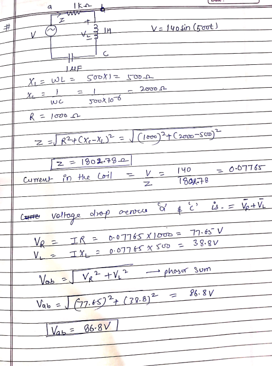
Determine the maximum voltage drop between "a" and "c" points in the circuit. d 1uF Ο...
For a RC circuit if C- 1uF and the DC source voltage is 12 V, design...
 For a RC circuit if C- 1uF and the DC source voltage is 12 V, design the resistor R such that the capacitor voltage reaches 10v 15 sec after the switch is closed ? What is the time constant of the resulting circuit? (5 pts) Switch S E, 9 b) How does the capacitive reactance of a 1 micro-farad capacitor and the inductive reactance of a 10 milli-henry inductor change in a AC circuit when the frequency changes from 50...
With solar panels, can you determine an approximate relationship between drop in maximum power voltage and the number of...
With solar panels, can you determine an approximate relationship between drop in maximum power voltage and the number of switched on diodes and by-passed cells?
Voltage or No Voltage? A This circuit has four "test points" labeled with the letters A,...
 Voltage or No Voltage? A This circuit has four "test points" labeled with the letters A, B, C, and D. Assuming the circuit is functioning (light bulb is energized), determine whether or not there will be substantial voltage between the following sets of points: Between A and B: voltage or no voltage? Between B and C: voltage or no voltage? Between C and D: voltage or no voltage? Between D and A: voltage or no voltage? Between A and C:...
For the following circuit: At t=0 the voltage drop on the capacitor is and points s...
 For the following circuit:
At t=0 the voltage drop on the capacitor is and
points s and 1 are connected.
1) Which of the following statement describe what will happen in
the circuit ? (select one)
a. The capacitor will be charged to a final voltage of , with I
being the current in the circuit
b. The capacitor will disconnect the circuit so no current will
exist
c. The voltage will oscillate at an angular frequency of
d. The...
For the following circuit:
At t=0 the voltage drop on the capacitor is and
points s and 1 are connected.
1) Which of the following statement describe what will happen in
the circuit ? (select one)
a. The capacitor will be charged to a final voltage of , with I
being the current in the circuit
b. The capacitor will disconnect the circuit so no current will
exist
c. The voltage will oscillate at an angular frequency of
d. The...
Problem # 3 Determine the voltage drop and the current through each resistor in a circuit...
Problem # 3 Determine the voltage drop and the current through each resistor in a circuit composed of three resistors (5, 10 and 20 ohms) connected in parallel with a 12 V voltage source.
3. A) Use node-voltage analysis to determine the Thevenin voltage between points A and B in...
 3. A) Use node-voltage analysis to determine the Thevenin voltage between points A and B in this circuit. B) determine the Thevenin resistance between points A and B. 9.00V 14.0V 一日 <5602 S8102 47021 10000
• For the circuit in Figure 1, assume that the voltage drop across the infrared emitter...
 • For the circuit in Figure 1, assume that the voltage drop
across the infrared emitter is 1.3 V. Determine the value of RE
that will limit the emitter current to a maximum of 50 mA.
• For the circuit in Figure 1, assume RX = 10 kΩ and VS = 5 V.
Using the equation given in the introduction section, determine the
value of RF needed to implement the Schmitt Trigger with a spread
or hysteresis value between 0.5...
• For the circuit in Figure 1, assume that the voltage drop
across the infrared emitter is 1.3 V. Determine the value of RE
that will limit the emitter current to a maximum of 50 mA.
• For the circuit in Figure 1, assume RX = 10 kΩ and VS = 5 V.
Using the equation given in the introduction section, determine the
value of RF needed to implement the Schmitt Trigger with a spread
or hysteresis value between 0.5...
Calculate the voltage at points A, B, and C, in the following circuit. Find the power...
 Calculate the voltage at points A, B, and C, in the following circuit. Find the power dissipated by each resistor. 6 V Calculate the total current I flowing through the following circuit segment. Then, find the voltage drop across each resistor. -18 V 12 kΩ 12 k
Q1. (3 marks) In the circuit shown below, R-1.5KO and the voltage drop across Ri is...
 Q1. (3 marks) In the circuit shown below, R-1.5KO and the voltage drop across Ri is 4.5V. (1 pt.) A. What is the voltage drop across R? (1 pt.) B. What is the value of the resistance R? (1 pt.) C. What is the power delivered by the source voltage? S Answer: wwiw R Ri Vs=15V Q2. (3 marks) Refer to the circuit below. A. Using the voltage divider law, find the voltage between the points A and B. B....
The LED's in the following circuit have forward voltage drop of 2 volts. Determine R1 and...
 The LED's in the following circuit have forward voltage drop of 2 volts. Determine R1 and R2 so that each LED has a current of 20 mA. KR
 For a RC circuit if C- 1uF and the DC source voltage is 12 V, design the resistor R such that the capacitor voltage reaches 10v 15 sec after the switch is closed ? What is the time constant of the resulting circuit? (5 pts) Switch S E, 9 b) How does the capacitive reactance of a 1 micro-farad capacitor and the inductive reactance of a 10 milli-henry inductor change in a AC circuit when the frequency changes from 50...
 Voltage or No Voltage? A This circuit has four "test points" labeled with the letters A, B, C, and D. Assuming the circuit is functioning (light bulb is energized), determine whether or not there will be substantial voltage between the following sets of points: Between A and B: voltage or no voltage? Between B and C: voltage or no voltage? Between C and D: voltage or no voltage? Between D and A: voltage or no voltage? Between A and C:...
 For the following circuit:
At t=0 the voltage drop on the capacitor is and
points s and 1 are connected.
1) Which of the following statement describe what will happen in
the circuit ? (select one)
a. The capacitor will be charged to a final voltage of , with I
being the current in the circuit
b. The capacitor will disconnect the circuit so no current will
exist
c. The voltage will oscillate at an angular frequency of
d. The...
For the following circuit:
At t=0 the voltage drop on the capacitor is and
points s and 1 are connected.
1) Which of the following statement describe what will happen in
the circuit ? (select one)
a. The capacitor will be charged to a final voltage of , with I
being the current in the circuit
b. The capacitor will disconnect the circuit so no current will
exist
c. The voltage will oscillate at an angular frequency of
d. The...
 3. A) Use node-voltage analysis to determine the Thevenin voltage between points A and B in this circuit. B) determine the Thevenin resistance between points A and B. 9.00V 14.0V 一日 <5602 S8102 47021 10000
 • For the circuit in Figure 1, assume that the voltage drop
across the infrared emitter is 1.3 V. Determine the value of RE
that will limit the emitter current to a maximum of 50 mA.
• For the circuit in Figure 1, assume RX = 10 kΩ and VS = 5 V.
Using the equation given in the introduction section, determine the
value of RF needed to implement the Schmitt Trigger with a spread
or hysteresis value between 0.5...
• For the circuit in Figure 1, assume that the voltage drop
across the infrared emitter is 1.3 V. Determine the value of RE
that will limit the emitter current to a maximum of 50 mA.
• For the circuit in Figure 1, assume RX = 10 kΩ and VS = 5 V.
Using the equation given in the introduction section, determine the
value of RF needed to implement the Schmitt Trigger with a spread
or hysteresis value between 0.5...
 Calculate the voltage at points A, B, and C, in the following circuit. Find the power dissipated by each resistor. 6 V Calculate the total current I flowing through the following circuit segment. Then, find the voltage drop across each resistor. -18 V 12 kΩ 12 k
 Q1. (3 marks) In the circuit shown below, R-1.5KO and the voltage drop across Ri is 4.5V. (1 pt.) A. What is the voltage drop across R? (1 pt.) B. What is the value of the resistance R? (1 pt.) C. What is the power delivered by the source voltage? S Answer: wwiw R Ri Vs=15V Q2. (3 marks) Refer to the circuit below. A. Using the voltage divider law, find the voltage between the points A and B. B....
 The LED's in the following circuit have forward voltage drop of 2 volts. Determine R1 and R2 so that each LED has a current of 20 mA. KR
Most questions answered within 3 hours.
-
A large cable company reports the following.
80% of its customers subscribe to its cable TV...
asked 14 minutes ago -
Please answer the question in brief.
Discuss the role of ERP in organizations. Are ERP tools...
asked 27 seconds ago -
Discuss the pros and cons of collaborative software such
as SameTime. Does it increase productivity? What...
asked 12 minutes ago -
1. Are all good samples random?
2. Magazines often report surveys giving statistics such as “63%...
asked 7 minutes ago -
Buying your in-laws a gift because it’s expected is
due to the ____________ motive of gift-giving....
asked 16 minutes ago -
Calculate the expected value, the variance, and the standard
deviation of the given random variable X....
asked 59 minutes ago -
A hospital performs 100 surgeries per week. The probability that
complications after surgery occur is 10%....
asked 1 hour ago -
1 point) Given the significance level α=0.01 find the following:
(a) left-tailed z value z= (b)...
asked 57 minutes ago -
Assuming you are the head of the software development unit at
Cyber.Soft, explain and justify why...
asked 23 minutes ago -
Magnesium and nitrogen react in a combination reaction to
produce magnesium nitride. 3 Mg + N2...
asked 31 minutes ago -
Two electrons are initially at rest separated by a distance of
2nm. At time t=0, they...
asked 29 minutes ago -
A martial artist is practicing breaking 5 boards. He is able to
break aboard with probability...
asked 36 minutes ago