![X=0 x = 1/2 x= L u U2 Uz (a) Trial solution for a 1-D quadratic elastic bar element can be written as follows: ū(x) = [N]{u}](http://img.homeworklib.com/questions/7a06b2f0-cce8-11eb-981c-07362aa339cb.png?x-oss-process=image/resize,w_560)
Homework Answers


x = linspace(0,1,11)';
L = 1;
N1 = [(2*x.^2-3*L*x+L^2)/L^2 -4*(x.^2-L*x)/L^2
(2*x.^2-L*x)/L^2];
u1 = 1.0e-03 *[ 0 ; 0.0573; 0.1042];
u = N1*u1;
plot(x,u)
hold on
x = linspace(0,1/2,6)';
L = 1/2;
N1 = [(2*x.^2-3*L*x+L^2)/L^2 -4*(x.^2-L*x)/L^2
(2*x.^2-L*x)/L^2];
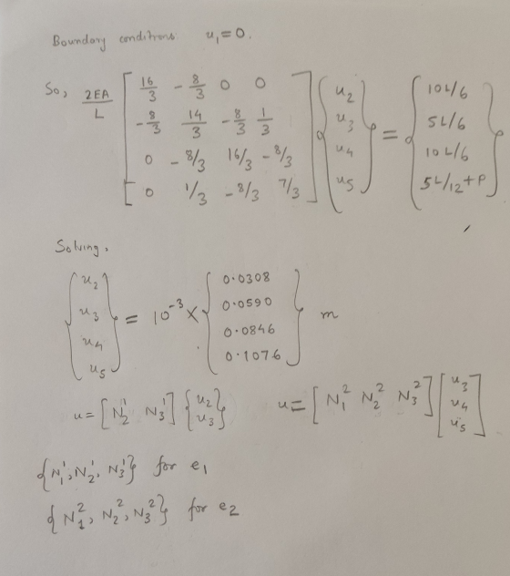
u1 = 1.0e-03 *[0; 0.0308; 0.0590];
u1 = N1*u1;
x = linspace(0,1/2,6)';
L = 1/2;
N1 = [(2*x.^2-3*L*x+L^2)/L^2 -4*(x.^2-L*x)/L^2
(2*x.^2-L*x)/L^2];
u2 = 1.0e-03 *[ 0.0590; 0.0846; 0.1076];
u2 = N1*u2;
u = [u1(1:end-1);u2];
plot( linspace(0,1,11),u)
legend('1 element','2 elements')

(40 pts) 2a. Show that u(z) is the solution to the problem where k(x)-1 for x < 1/2 and k = 2 for...
 (40 pts) 2a. Show that u(z) is the solution to the problem where k(x)-1 for x < 1/2 and k = 2 for x > 1 /2. 2b. Set up the weak form for the differential equation above and the resulting element stiffness and element load vector and calculate the element stiffness matrix and load vector for 4 quadratic elements by using the Gaussian quadrature that is going to exactly calculate the integrals Then set up the global K and...
Question 1: For the plane (2D) truss shown below, evaluate the transformation matrix [T] and the stiffness matrix in the local axis system [KL] of all elements. Use these matrices to evaluate the ele...
 Question 1: For the plane (2D) truss shown below, evaluate the transformation matrix [T] and the stiffness matrix in the local axis system [KL] of all elements. Use these matrices to evaluate the element stiffness matrix in global axis system [KG] of the members and assembled them to generate the overall stiffness matrix [K of the truss. Modify the stiffness matrix [K] in order to incorporate boundary conditions following the elimination technique of rows and columns. Take E 200 GPa...
For the plane bar trusses shown in Figure 2. All bar elements have E= 210GPa and A-4.0 x 10⁻⁴ m2....
 For the plane bar trusses shown in Figure 2. All bar elements have E= 210GPa and A-4.0 x 10⁻⁴ m2. Note: 1GPa=UPKN/m? 3 m 45° IO KN 3 m 20 kN FIG. 3: Plane trusses Determine: element 1 stiffness matrix element 2 stiffness matrix, element 3 stiffness matrix global stiffness matrix [K], global balance equation, boundary conditions, the horizontal displacement of node1 the vertical displacement of node 1 the horizontal reaction force at node 3, the vertical reaction force at...
For the spring assemblage shown in Figure 2-13, obtain (a) the global stiffness matrix, (b) the displacements of nodes 2-4, (c) the global nodal forces, and (d) the local element forces.
For the spring assemblage shown in Figure 2-13, obtain (a) the global stiffness matrix, (b) the displacements of nodes 2-4, (c) the global nodal forces, and (d) the local element forces. Node l is fixed while node 5 is given a fixed, known displacement δ= 20.0 mm. The spring constants are all equal to k = 200 kN/m.
Consider the frame in Fig. 1, the node and element numbers as well as the material and geometrica...
 Consider the frame in Fig. 1, the node and element numbers as well as the material and geometrical characteristics of the beam elements are also displayed on the same figure. The frame is subjected to two concentrated loads at nodes 2 and 3 and a uniform distributed load over beam 3. The frame is fixed at nodes 1 and 5. A global coordinate system is established with origin at node 1 and x-y axes positively directed to the right and...
2) (30 points) The 2-segment bar shown below is loaded by an axial force f(x) and...
 2) (30 points) The 2-segment bar shown below is loaded by an axial force f(x) and is fixed at both ends. Develop the finite element model of the bar using two linear elements. Note that the 3 nodes are shown and labeled. Use the following data: Ej = E2 = 200 GPa Aj = 0.01 m² A2 = 0.005 m² Li = L2 = 1 m f(x) = 3e7.x N/m HX f(x) - - 1 E1, A1,47 - - 2...
Solve the following truss problem. All truss members are ANSI 2x2x0.25 hollow square tubes (with rounded...
 Solve the following truss problem. All truss members are ANSI 2x2x0.25 hollow square tubes (with rounded corners) for which the cross-section area is A-1.5891 in2. The material has a modulus of E-29E6 psi. Length of element 1 and 5 is L-20 inches, and length of element 3 and 6 is 2L 40 inches. 7 5 6 P-1000 lb 2. 1. Solve in an Excel spreadsheet using the truss element. Note that there are only four different element stiffness matrices (look...
Section 1: Finite Element Derivation and Validation In this section of the report you will develop your own Finite Elem...
 Section 1: Finite Element Derivation and Validation In this section of the report you will develop your own Finite Element method for 1-dimensional axial loading. The governing equation for displacement, u is Poisson's Equation: อั1 where E is the modulus of elasticity, A(a) is the cross-sectional area as a function of length, and q(x) is the loading distribution as a function of length. The weak form of this equation with 0 1. Starting from the weak form of the governing...
need to solve the mathematical model to prove that we can get the equations i Q1...
 need to solve the mathematical model to prove
that we can get the equations i Q1 a methematically
QI. A vertical pile is used to transfer the vertical load from the soft ground surface to the rock surface. It is assumed that the stiffness of the rock is sufficient to prevent any vertical displacement so that the lower edge of the rod may be considered as fixed. The soft ground acts on the pile along its length with a force...
need to solve the mathematical model to prove
that we can get the equations i Q1 a methematically
QI. A vertical pile is used to transfer the vertical load from the soft ground surface to the rock surface. It is assumed that the stiffness of the rock is sufficient to prevent any vertical displacement so that the lower edge of the rod may be considered as fixed. The soft ground acts on the pile along its length with a force...
Problem 1: Axial vibrations of a rod The rod of length L is fixed at ends x = 0 and x = L. The de...
 Problem 1: Axial vibrations of a rod The rod of length L is fixed at ends x = 0 and x = L. The density of the rod is ρ(x), stiffness k(x) being subjected to a force f(x, t). Let's derive the equations for axial vibrations of a rod using almped model. We express the rod niy mol 41 in as a chain of masses m,mm, connected to each other through springs as shown in the figure. Let's say each...
 (40 pts) 2a. Show that u(z) is the solution to the problem where k(x)-1 for x < 1/2 and k = 2 for x > 1 /2. 2b. Set up the weak form for the differential equation above and the resulting element stiffness and element load vector and calculate the element stiffness matrix and load vector for 4 quadratic elements by using the Gaussian quadrature that is going to exactly calculate the integrals Then set up the global K and...
 Question 1: For the plane (2D) truss shown below, evaluate the transformation matrix [T] and the stiffness matrix in the local axis system [KL] of all elements. Use these matrices to evaluate the element stiffness matrix in global axis system [KG] of the members and assembled them to generate the overall stiffness matrix [K of the truss. Modify the stiffness matrix [K] in order to incorporate boundary conditions following the elimination technique of rows and columns. Take E 200 GPa...
 For the plane bar trusses shown in Figure 2. All bar elements have E= 210GPa and A-4.0 x 10⁻⁴ m2. Note: 1GPa=UPKN/m? 3 m 45° IO KN 3 m 20 kN FIG. 3: Plane trusses Determine: element 1 stiffness matrix element 2 stiffness matrix, element 3 stiffness matrix global stiffness matrix [K], global balance equation, boundary conditions, the horizontal displacement of node1 the vertical displacement of node 1 the horizontal reaction force at node 3, the vertical reaction force at...
 Consider the frame in Fig. 1, the node and element numbers as well as the material and geometrical characteristics of the beam elements are also displayed on the same figure. The frame is subjected to two concentrated loads at nodes 2 and 3 and a uniform distributed load over beam 3. The frame is fixed at nodes 1 and 5. A global coordinate system is established with origin at node 1 and x-y axes positively directed to the right and...
 2) (30 points) The 2-segment bar shown below is loaded by an axial force f(x) and is fixed at both ends. Develop the finite element model of the bar using two linear elements. Note that the 3 nodes are shown and labeled. Use the following data: Ej = E2 = 200 GPa Aj = 0.01 m² A2 = 0.005 m² Li = L2 = 1 m f(x) = 3e7.x N/m HX f(x) - - 1 E1, A1,47 - - 2...
 Solve the following truss problem. All truss members are ANSI 2x2x0.25 hollow square tubes (with rounded corners) for which the cross-section area is A-1.5891 in2. The material has a modulus of E-29E6 psi. Length of element 1 and 5 is L-20 inches, and length of element 3 and 6 is 2L 40 inches. 7 5 6 P-1000 lb 2. 1. Solve in an Excel spreadsheet using the truss element. Note that there are only four different element stiffness matrices (look...
 Section 1: Finite Element Derivation and Validation In this section of the report you will develop your own Finite Element method for 1-dimensional axial loading. The governing equation for displacement, u is Poisson's Equation: อั1 where E is the modulus of elasticity, A(a) is the cross-sectional area as a function of length, and q(x) is the loading distribution as a function of length. The weak form of this equation with 0 1. Starting from the weak form of the governing...
 need to solve the mathematical model to prove
that we can get the equations i Q1 a methematically
QI. A vertical pile is used to transfer the vertical load from the soft ground surface to the rock surface. It is assumed that the stiffness of the rock is sufficient to prevent any vertical displacement so that the lower edge of the rod may be considered as fixed. The soft ground acts on the pile along its length with a force...
need to solve the mathematical model to prove
that we can get the equations i Q1 a methematically
QI. A vertical pile is used to transfer the vertical load from the soft ground surface to the rock surface. It is assumed that the stiffness of the rock is sufficient to prevent any vertical displacement so that the lower edge of the rod may be considered as fixed. The soft ground acts on the pile along its length with a force...
 Problem 1: Axial vibrations of a rod The rod of length L is fixed at ends x = 0 and x = L. The density of the rod is ρ(x), stiffness k(x) being subjected to a force f(x, t). Let's derive the equations for axial vibrations of a rod using almped model. We express the rod niy mol 41 in as a chain of masses m,mm, connected to each other through springs as shown in the figure. Let's say each...
Most questions answered within 3 hours.
-
An empty test tube weighs 15.923 grams. Then,
MgCl2•6H2O is added into the test tube. After...
asked 29 minutes ago -
Please answer true or false. Words
cannot be changed or added in to make it true...
asked 27 minutes ago -
(a) A piston at 6.1 atm contains a gas that occupies a volume of
3.5 L....
asked 28 minutes ago -
Assume memory access is 10 units of time and disk access is
10000 units of time....
asked 47 minutes ago -
1. Are all good samples random?
2. Magazines often report surveys giving statistics such as “63%...
asked 1 hour ago -
Under all the various types of market structures, firms
must eventually earn some economic profits for...
asked 54 minutes ago -
Consider the following fitness regime for a single locus trait
with two co-dominant alleles: w11 =...
asked 59 minutes ago -
A large cable company reports the following.
80% of its customers subscribe to its cable TV...
asked 1 hour ago -
Please answer the question in brief.
Discuss the role of ERP in organizations. Are ERP tools...
asked 1 hour ago -
Discuss the pros and cons of collaborative software such
as SameTime. Does it increase productivity? What...
asked 1 hour ago -
Buying your in-laws a gift because it’s expected is
due to the ____________ motive of gift-giving....
asked 1 hour ago -
Calculate the expected value, the variance, and the standard
deviation of the given random variable X....
asked 1 hour ago