![Question 1: For the plane (2D) truss shown below, evaluate the transformation matrix [T] and the stiffness matrix in the loca](http://img.homeworklib.com/images/a34b99d1-ca9f-4e17-bd28-2f40e5849be5.png?x-oss-process=image/resize,w_560)
Homework Answers


Add Answer to:
Question 1: For the plane (2D) truss shown below, evaluate the transformation matrix [T] and the stiffness matrix in the local axis system [KL] of all elements. Use these matrices to evaluate the ele...
1. (60%) For the truss system shown below (a) (12%) Determine the element stiffness matrix w.r.t....
 1. (60%) For the truss system shown below (a) (12%) Determine the element stiffness matrix w.r.t. the global coordinate system for all elements. (b) (10%) Determine the global stiffness matrix, [K]. (c) (5%) List all the boundary conditions. (d) (33%) Determine the internal force, elongation, stress, and strain for each element. Indicate whether it is under tension or compression. My LLLLLLLL 1 0 1-2=45° \ 30° 30° / 14116 141 16 12 2-3 = 30 3 1-4=300 Join But 45=225...
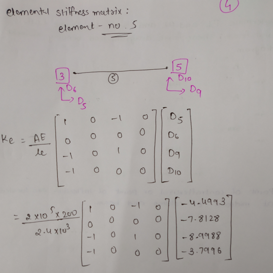
For the truss shown in the figure below, develop element stiffness matrices in the global co-ordinate system. AE 200 [M...
 For the truss shown in the figure below, develop element stiffness matrices in the global co-ordinate system. AE 200 [MN] is the same for all members. Use the direct stiffness matrix method to: i. Establish all element stiffness matrices in global coordinates ii.Find the displacements in node 3 ii. Calculate the member stresses 4m 3m 20kN 2 2 Use HELM resources on Moodle to find required determinant and inverse matrix. Answer 9.6x10³ [MPa] 0.24mmm u3-0.20mm 0.45mm 16x10-3 MPa σ2-3- 1...
For the 3-D indeterminate (4-member) TRUSS structure shown in Figure 2A. Given that Px 10K (in...
 For the 3-D indeterminate (4-member) TRUSS structure shown in Figure 2A. Given that Px 10K (in X-direction); Py none (in Y-direction); E 30,000 ksi; A 0.2 square inches. The nodal coordinates, the earth-quake displacement/settlement, and members' connectivity information are given aS Applied Load! Earth-Quake MEMBER #1 NODE # X node-i node-j 120.00" 160.00"| 80.00"| Px=-10 Kips none Py- none 120.00" 160.00"0.00"none 120.00"0.00" 0.00" none 0.00" 0.00"0.00" none 0.00" 0.00" 80.00" none none 2 none 4 4 none 4 +2.00" (in...
A plane structure consists of three truss elements connected to four nodes, as shown below. All t...
 A plane structure consists of three truss elements connected to four nodes, as shown below. All trusses have cross sectional area A -7.104 m2 and elastic modulus E = 210 GPa. The length of each truss element is L = 1 m. A point force, P -5 kN, is acting on node 4 L/2 3.1 Calculate the displacements at the nodes 3.2 Calculate the reaction forces 3.3 Calculate the stress in each bar
A plane structure consists of three truss...
A plane structure consists of three truss elements connected to four nodes, as shown below. All trusses have cross sectional area A -7.104 m2 and elastic modulus E = 210 GPa. The length of each truss element is L = 1 m. A point force, P -5 kN, is acting on node 4 L/2 3.1 Calculate the displacements at the nodes 3.2 Calculate the reaction forces 3.3 Calculate the stress in each bar
A plane structure consists of three truss...
i need help with c and d but explain why Question 1 (10 marks). Assembly A model consists of two 1D trusses with dimens...
 i need help with c and d but explain why
Question 1 (10 marks). Assembly A model consists of two 1D trusses with dimensions as given in Figure 1. Element 1 runs angle, connecting parallel to the x-axis, connecting node 1 and 2. Element 2 is running at an node 1 and 3. Node 1 has an applied force in the negative y-direction. Node 1 can only in y-direction, while nodes 2 and 3 are fixed in both x and...
i need help with c and d but explain why
Question 1 (10 marks). Assembly A model consists of two 1D trusses with dimensions as given in Figure 1. Element 1 runs angle, connecting parallel to the x-axis, connecting node 1 and 2. Element 2 is running at an node 1 and 3. Node 1 has an applied force in the negative y-direction. Node 1 can only in y-direction, while nodes 2 and 3 are fixed in both x and...
Week 9. Question 1: Use the stiffness method to analyse the structure shown below. For the...
 Week 9. Question 1: Use the stiffness method to analyse the structure shown below. For the beam ABC, E = 2 -10% kPa, A -00, = 1.2e - 4 m. For the truss member DB, E = 200000000 kPa, A = 0.002 m. Also, take L54 m and w37 kN/m с 7 Degrees of freedom 22 Calculate the the bending moment at Joint B following the steps below. Part 1: Assemble the global structure stiffness matrix. Note that ABC is...
Week 9, Question 1: Use the stiffness method to analyse the structure shown below. For the...
 Week 9, Question 1: Use the stiffness method to analyse the structure shown below. For the beam ABC, E = 2-108 kPa, A=00, I = 1.2e - 4 mº.. For the truss member DB, E = 200000000 kPa, A=0.002 m2. Also, take L=6.9 m and w=30 kN/m. Degrees of freedom l- _-2L Calculate the the bending moment at Joint B following the steps below: Part 1: Assemble the global structure stiffness matrix. Note that ABC is infinitely rigid in the...
Week 9, Question 1: Use the stiffness method to analyse the structure shown below. For the...
 Week 9, Question 1: Use the stiffness method to analyse the structure shown below. For the beam ABC, E = 2.108 kPa, A = 0,1 = 1.2e – 4 mº.. For the truss member DB, E = 200000000 kPa, A = 0.002 m². Also, take L = 4.8 m and a = 25 kN/m. 0 2 A B C III 7 L 3 4 Degrees of freedom D L -2L Calculate the the bending moment at Joint B following the...
Week 9, Question 2: Use the stiffness method to analyse the elastic frame ABC shown below....
 Week 9, Question 2: Use the stiffness method to analyse the elastic frame ABC shown below. Use a model made up of 2 the elements (AB and CB) and the axis indicated in the figure. All members have the following properties: E = 2 ·10kPa, A = 0.005 m², 1 = 1.5e – 4 m+.. Also the lengths of the elements are the same: AB = BC = L = 6.5 m and w = 12 kN/m. 0 А x...
 1. (60%) For the truss system shown below (a) (12%) Determine the element stiffness matrix w.r.t. the global coordinate system for all elements. (b) (10%) Determine the global stiffness matrix, [K]. (c) (5%) List all the boundary conditions. (d) (33%) Determine the internal force, elongation, stress, and strain for each element. Indicate whether it is under tension or compression. My LLLLLLLL 1 0 1-2=45° \ 30° 30° / 14116 141 16 12 2-3 = 30 3 1-4=300 Join But 45=225...
 For the truss shown in the figure below, develop element stiffness matrices in the global co-ordinate system. AE 200 [MN] is the same for all members. Use the direct stiffness matrix method to: i. Establish all element stiffness matrices in global coordinates ii.Find the displacements in node 3 ii. Calculate the member stresses 4m 3m 20kN 2 2 Use HELM resources on Moodle to find required determinant and inverse matrix. Answer 9.6x10³ [MPa] 0.24mmm u3-0.20mm 0.45mm 16x10-3 MPa σ2-3- 1...
 For the 3-D indeterminate (4-member) TRUSS structure shown in Figure 2A. Given that Px 10K (in X-direction); Py none (in Y-direction); E 30,000 ksi; A 0.2 square inches. The nodal coordinates, the earth-quake displacement/settlement, and members' connectivity information are given aS Applied Load! Earth-Quake MEMBER #1 NODE # X node-i node-j 120.00" 160.00"| 80.00"| Px=-10 Kips none Py- none 120.00" 160.00"0.00"none 120.00"0.00" 0.00" none 0.00" 0.00"0.00" none 0.00" 0.00" 80.00" none none 2 none 4 4 none 4 +2.00" (in...
 A plane structure consists of three truss elements connected to four nodes, as shown below. All trusses have cross sectional area A -7.104 m2 and elastic modulus E = 210 GPa. The length of each truss element is L = 1 m. A point force, P -5 kN, is acting on node 4 L/2 3.1 Calculate the displacements at the nodes 3.2 Calculate the reaction forces 3.3 Calculate the stress in each bar
A plane structure consists of three truss...
A plane structure consists of three truss elements connected to four nodes, as shown below. All trusses have cross sectional area A -7.104 m2 and elastic modulus E = 210 GPa. The length of each truss element is L = 1 m. A point force, P -5 kN, is acting on node 4 L/2 3.1 Calculate the displacements at the nodes 3.2 Calculate the reaction forces 3.3 Calculate the stress in each bar
A plane structure consists of three truss...
 i need help with c and d but explain why
Question 1 (10 marks). Assembly A model consists of two 1D trusses with dimensions as given in Figure 1. Element 1 runs angle, connecting parallel to the x-axis, connecting node 1 and 2. Element 2 is running at an node 1 and 3. Node 1 has an applied force in the negative y-direction. Node 1 can only in y-direction, while nodes 2 and 3 are fixed in both x and...
i need help with c and d but explain why
Question 1 (10 marks). Assembly A model consists of two 1D trusses with dimensions as given in Figure 1. Element 1 runs angle, connecting parallel to the x-axis, connecting node 1 and 2. Element 2 is running at an node 1 and 3. Node 1 has an applied force in the negative y-direction. Node 1 can only in y-direction, while nodes 2 and 3 are fixed in both x and...
 Week 9. Question 1: Use the stiffness method to analyse the structure shown below. For the beam ABC, E = 2 -10% kPa, A -00, = 1.2e - 4 m. For the truss member DB, E = 200000000 kPa, A = 0.002 m. Also, take L54 m and w37 kN/m с 7 Degrees of freedom 22 Calculate the the bending moment at Joint B following the steps below. Part 1: Assemble the global structure stiffness matrix. Note that ABC is...
 Week 9, Question 1: Use the stiffness method to analyse the structure shown below. For the beam ABC, E = 2-108 kPa, A=00, I = 1.2e - 4 mº.. For the truss member DB, E = 200000000 kPa, A=0.002 m2. Also, take L=6.9 m and w=30 kN/m. Degrees of freedom l- _-2L Calculate the the bending moment at Joint B following the steps below: Part 1: Assemble the global structure stiffness matrix. Note that ABC is infinitely rigid in the...
 Week 9, Question 1: Use the stiffness method to analyse the structure shown below. For the beam ABC, E = 2.108 kPa, A = 0,1 = 1.2e – 4 mº.. For the truss member DB, E = 200000000 kPa, A = 0.002 m². Also, take L = 4.8 m and a = 25 kN/m. 0 2 A B C III 7 L 3 4 Degrees of freedom D L -2L Calculate the the bending moment at Joint B following the...
 Week 9, Question 2: Use the stiffness method to analyse the elastic frame ABC shown below. Use a model made up of 2 the elements (AB and CB) and the axis indicated in the figure. All members have the following properties: E = 2 ·10kPa, A = 0.005 m², 1 = 1.5e – 4 m+.. Also the lengths of the elements are the same: AB = BC = L = 6.5 m and w = 12 kN/m. 0 А x...
Most questions answered within 3 hours.
-
Katelynn, a physician, earns $200,000 from her medical practice
in the current year. She receives $45,000...
asked 5 minutes ago -
Each row of the table below describes an aqueous solution at
25°C
.
The second column...
asked 9 minutes ago -
A horizontal wire is at y = 0. Current travels in the +x
direction. The magnetic...
asked 10 minutes ago -
Let X be a continuous random variable whose PDF is Let X be a
continuous random...
asked 31 minutes ago -
Martinez Company’s relevant range of production is 7,500 units
to 12,500 units. When it produces and...
asked 29 minutes ago -
A football with a mass of 1.2 kg is kicked from ground level to
a height...
asked 35 minutes ago -
Remember: Changes in supply determinants shift supply, and
changes in demand determinants shift demand. We say...
asked 33 minutes ago -
Why is the answer b), for this question? I came up with C) for
my incorrect...
asked 39 minutes ago -
Suppose that you know that in the population of full-time
employees in the United States, the...
asked 1 hour ago -
This experiment was designed originally to sample various meat and carcass quality
aspects of Ontario pigs...
asked 1 hour ago -
Dopamine Hydrochloride: draw the structure And Show the
functional groups in different colors and label the...
asked 54 minutes ago -
A rope supports a 10 kg dumbbell hanging from it. What is the
tension in the...
asked 53 minutes ago