

Homework Answers

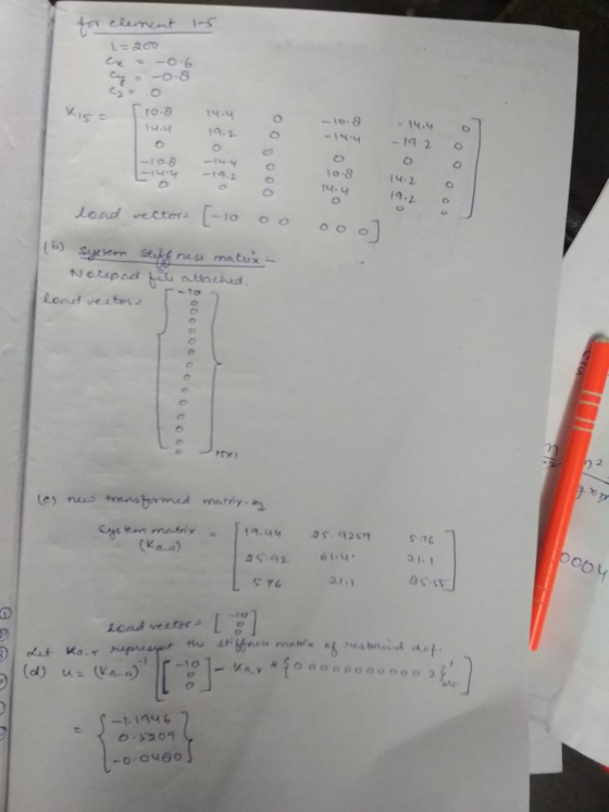


b) system stiffness matrix - k_G =
Columns 1 through 12
19.4444 25.9259 5.7630 0 0 0 0 0 0 -8.6444 -11.5259
-5.7630
25.9259 61.4007 21.1004 0 0 0 0 -26.8328 -13.4164 -11.5259 -15.3679
-7.6839
5.7630 21.1004 85.5502 0 0 -75.0000 0 -13.4164 -6.7082 -5.7630
-7.6839 -3.8420
0 0 0 0 0 0 0 0 0 0 0 0
0 0 0 0 0 0 0 0 0 0 0 0
0 0 -75.0000 0 0 75.0000 0 0 0 0 0 0
0 0 0 0 0 0 0 0 0 0 0 0
0 -26.8328 -13.4164 0 0 0 0 26.8328 13.4164 0 0 0
0 -13.4164 -6.7082 0 0 0 0 13.4164 6.7082 0 0 0
-8.6444 -11.5259 -5.7630 0 0 0 0 0 0 8.6444 11.5259 5.7630
-11.5259 -15.3679 -7.6839 0 0 0 0 0 0 11.5259 15.3679 7.6839
-5.7630 -7.6839 -3.8420 0 0 0 0 0 0 5.7630 7.6839 3.8420
-10.8000 -14.4000 0 0 0 0 0 0 0 0 0 0
-14.4000 -19.2000 0 0 0 0 0 0 0 0 0 0
0 0 0 0 0 0 0 0 0 0 0 0
Columns 13 through 15
-10.8000 -14.4000 0
-14.4000 -19.2000 0
0 0 0
0 0 0
0 0 0
0 0 0
0 0 0
0 0 0
0 0 0
0 0 0
0 0 0
0 0 0
10.8000 14.4000 0
14.4000 19.2000 0
0 0 0
attaching a MATLAB code. it will be helpul always.
clear all;
clc;
tic;
E=30000;
A=.2;
Con=[1 2;1 3;1 4;1 5];
node_vec=unique(reshape(Con',1,[]));
node=numel(node_vec);
dof1=3;
dof=[];
for i=1:node
dof=[dof;dof1*i-dof1+1, dof1*i-dof1+2, dof1*i-dof1+3];
end
dof_vec=unique(reshape(dof',1,[]));
ndof_tot=numel(dof_vec);
dof_R=[4:15];
dof_A=setdiff(dof_vec,dof_R);
del_R=zeros(numel(dof_R),1);
del_R(12)=2;
p=1
del=zeros(ndof_tot,1);
F=zeros(ndof_tot,1);
F(1)=-10;
F_A=F(dof_A);
x=[120 120 120 0 0];
y=[160 160 0 0 0];
z =[80 0 0 0 80];
Coord=[x' y' z'];
nmem=size(Con,1);
areapop=ones(nmem,1)*.2;
nCoord=size(Coord,1);
k_G=zeros(dof1*node);
for i=1:size(Con,1)
% coordinates of first node of element
x1=Coord(Con(i,1),1);
y1=Coord(Con(i,1),2);
z1=Coord(Con(i,1),3);
%coordinates of second node of element
x2=Coord(Con(i,2),1);
y2=Coord(Con(i,2),2);
z2=Coord(Con(i,2),3);
L=sqrt((x2-x1)^2+(y2-y1)^2+(z2-z1)^2);
cx= (x2-x1)/L;
cy= (y2-y1)/L;
cz= (z2-z1)/L;
T=[cx cy cz 0 0 0
0 0 0 0 0 0
0 0 0 0 0 0
0 0 0 cx cy cz
0 0 0 0 0 0
0 0 0 0 0 0];
k_loc= E*A/L*[1 0 0 -1 0 0
0 0 0 0 0 0
0 0 0 0 0 0
-1 0 0 1 0 0
0 0 0 0 0 0
0 0 0 0 0 0];
k=T'*k_loc*T;
ni=Con(i,:);
dii=dof(ni,:);
dj=reshape(dii',1,[]);
k_G(dj,dj)=k_G(dj,dj)+k;
end
k_RR=k_G(dof_R,dof_R);
k_RA=k_G(dof_R,dof_A);
k_AR=k_RA';
k_AA=k_G(dof_A,dof_A);
del_A=(k_AA)\(F_A-k_AR*del_R);
F_R=k_RR*del_R+k_RA*del_A;
del(dof_R,1)=del_R;
del(dof_A,1)=del_A;
F(dof_R)=F_R;
u1=del(1:dof1:end);
u2=del(2:dof1:end);
u3=del(3:dof1:end);
x_new=x+u1';
y_new=y+u2';
z_new=z+u3';
U=[u1' u2' u3'];
u(p)=max(U);
p=p+1;
k_G
Add Answer to:
For the 3-D indeterminate (4-member) TRUSS structure shown in Figure 2A. Given that Px 10K (in...
The plane truss is subjected to a load as shown in Figure 4. Take E = 200 GPa and cross sectional areas of members 1, 2...
 The plane truss is subjected to a load as shown in Figure 4. Take E = 200 GPa and cross sectional areas of members 1, 2 and 3 as 150, 250 and 200 mm2 respectively a) Assemble the upper triangular part of the global stiffness matrix for the truss b) Determine the horizontal and vertical displacements at node 4 c) Calculate the forces in each member of the truss. (25 marks) 20 kN 3 60° 4 1.5m 2 2 20m...
Question 4 The plane truss is subjected to a load as shown in Figure 4. Take E = 200 GPa and cross sectional areas of m...
 Question 4 The plane truss is subjected to a load as shown in Figure 4. Take E = 200 GPa and cross sectional areas of members 1, 2 and 3 as 150, 250 and 200 mm2 respectively a) Assemble the upper triangular part of the global stiffness matrix for the truss. b) Determine the horizontal and vertical displacements at node 4. c) Calculate the forces in each member of the truss. (25 marks) 20 kN 3 600 4 3 1.5m...
Finite Element Method 5.17 Displacements of the three-member truss shown are confined to the plane of...
 Finite Element Method
5.17 Displacements of the three-member truss shown are confined to the plane of the figure, and points 1, 2 and 3 are fixed to the stationary rim. All members have the same A, E, and L a) Obtain the 2x2 stiffness matrix that operates on the horizontal and vertical degrees of freedom of the central node. b) Obtain the corresponding global force vector c) Solve for the displacements and for axial stress in member (2-4), when the...
Finite Element Method
5.17 Displacements of the three-member truss shown are confined to the plane of the figure, and points 1, 2 and 3 are fixed to the stationary rim. All members have the same A, E, and L a) Obtain the 2x2 stiffness matrix that operates on the horizontal and vertical degrees of freedom of the central node. b) Obtain the corresponding global force vector c) Solve for the displacements and for axial stress in member (2-4), when the...
For the truss shown in the figure below, develop element stiffness matrices in the global co-ordinate system. AE 200 [M...
 For the truss shown in the figure below, develop element stiffness matrices in the global co-ordinate system. AE 200 [MN] is the same for all members. Use the direct stiffness matrix method to: i. Establish all element stiffness matrices in global coordinates ii.Find the displacements in node 3 ii. Calculate the member stresses 4m 3m 20kN 2 2 Use HELM resources on Moodle to find required determinant and inverse matrix. Answer 9.6x10³ [MPa] 0.24mmm u3-0.20mm 0.45mm 16x10-3 MPa σ2-3- 1...
2. For the pin-jointed truss shown in Figure Q2.1 applied at node 4. The Young's modulus E(GPa) is the same for...
 2. For the pin-jointed truss shown in Figure Q2.1 applied at node 4. The Young's modulus E(GPa) is the same for the three truss vertical downward force P(kN) is a members. The cross sectional area of each of the truss members is indicated below and expressed in terms of a constant A. By using the stiffness method: (a) Compute the reduced stiffness matrix Kg [5 marks [10 marks (b) Calculate the global displacements of node 4 in terms of P,...
Figure Q5(a) shows a plane truss supported by a horizontal spring at the top node. The...
 Figure Q5(a) shows a plane truss supported by a horizontal spring at the top node. The truss members are of a solid circular cross section having a diameter of 20 mm and an elastic modulus (E) of 80 GPa (10° N/m2). The spring has a stiffness constant of k-2000 kN/m. A point load of 15 kN is applied at the top node. The direction of the load is indicated in the figure. The code numbers for elements, nodes, DOFS, and...
Problem 2: The figure below shows a two-member plane truss supported by a linearly elastic spring....
 Problem 2: The figure below shows a two-member plane truss supported by a linearly elastic spring. The truss members are of a solid circular cross section having diameter, d = 20mm, and E = 80 GPa. The linear spring has a stiffness constant of 50 N/mm. A load of 15 kN is applied at 3 at an angle of 50 degrees with the horizontal. Find (a) The global displacements of the unconstrained node and (b) compute the reaction forces and...
Analyse the beam shown in Figure 4 using the stiffiness method. Node D is fixed and...
 Analyse the beam shown in Figure 4 using the stiffiness method. Node D is fixed and node 2 and 3 are rollers. A uniform distributed load of 1 kN/m is acting on member 1 . And a load of 10 kN is acting at the middle of member2. EI is constant for all members a) Identify the force vector of the structure; [4 marks] b) Identify the displacement vector of the structure; [2 marks] c) Determine the stiffness matrices of...
Problem 1 The truss (all joints are pinned) structure in figure 1 is made of members with cross s...
 We were unable to transcribe this imageProblem 1 The truss (all joints are pinned) structure in figure 1 is made of members with cross sectional area A = 1 in, with a linear elastic, homogeneous, isotropic material with an elastic modulus. E-10E6 psi and a coefficient of thermal expansion, α-6E-6 °F-ι. The structure starts out at a uniform temperature of 65°F and is raised to a final temperature of 120°F while being subjected to a concentrated load Po- 5,000 lbs...
3. A two bar truss structure is shown in Figure 1. The coordinates of Points A, C and B are given...
 3. A two bar truss structure is shown in Figure 1. The coordinates of Points A, C and B are given by (0,0), (0, 10") and (10",0), respectively, in which the x-axis is from A to B and the y-axis is from A to C. Points A and C are fixed. The cross-sectional area of all members in inch?. A vertical point load, P, is applied at the tip of the structure, Point B. Based upon either the Principle of...
 The plane truss is subjected to a load as shown in Figure 4. Take E = 200 GPa and cross sectional areas of members 1, 2 and 3 as 150, 250 and 200 mm2 respectively a) Assemble the upper triangular part of the global stiffness matrix for the truss b) Determine the horizontal and vertical displacements at node 4 c) Calculate the forces in each member of the truss. (25 marks) 20 kN 3 60° 4 1.5m 2 2 20m...
 Question 4 The plane truss is subjected to a load as shown in Figure 4. Take E = 200 GPa and cross sectional areas of members 1, 2 and 3 as 150, 250 and 200 mm2 respectively a) Assemble the upper triangular part of the global stiffness matrix for the truss. b) Determine the horizontal and vertical displacements at node 4. c) Calculate the forces in each member of the truss. (25 marks) 20 kN 3 600 4 3 1.5m...
 Finite Element Method
5.17 Displacements of the three-member truss shown are confined to the plane of the figure, and points 1, 2 and 3 are fixed to the stationary rim. All members have the same A, E, and L a) Obtain the 2x2 stiffness matrix that operates on the horizontal and vertical degrees of freedom of the central node. b) Obtain the corresponding global force vector c) Solve for the displacements and for axial stress in member (2-4), when the...
Finite Element Method
5.17 Displacements of the three-member truss shown are confined to the plane of the figure, and points 1, 2 and 3 are fixed to the stationary rim. All members have the same A, E, and L a) Obtain the 2x2 stiffness matrix that operates on the horizontal and vertical degrees of freedom of the central node. b) Obtain the corresponding global force vector c) Solve for the displacements and for axial stress in member (2-4), when the...
 For the truss shown in the figure below, develop element stiffness matrices in the global co-ordinate system. AE 200 [MN] is the same for all members. Use the direct stiffness matrix method to: i. Establish all element stiffness matrices in global coordinates ii.Find the displacements in node 3 ii. Calculate the member stresses 4m 3m 20kN 2 2 Use HELM resources on Moodle to find required determinant and inverse matrix. Answer 9.6x10³ [MPa] 0.24mmm u3-0.20mm 0.45mm 16x10-3 MPa σ2-3- 1...
 2. For the pin-jointed truss shown in Figure Q2.1 applied at node 4. The Young's modulus E(GPa) is the same for the three truss vertical downward force P(kN) is a members. The cross sectional area of each of the truss members is indicated below and expressed in terms of a constant A. By using the stiffness method: (a) Compute the reduced stiffness matrix Kg [5 marks [10 marks (b) Calculate the global displacements of node 4 in terms of P,...
 Figure Q5(a) shows a plane truss supported by a horizontal spring at the top node. The truss members are of a solid circular cross section having a diameter of 20 mm and an elastic modulus (E) of 80 GPa (10° N/m2). The spring has a stiffness constant of k-2000 kN/m. A point load of 15 kN is applied at the top node. The direction of the load is indicated in the figure. The code numbers for elements, nodes, DOFS, and...
 Problem 2: The figure below shows a two-member plane truss supported by a linearly elastic spring. The truss members are of a solid circular cross section having diameter, d = 20mm, and E = 80 GPa. The linear spring has a stiffness constant of 50 N/mm. A load of 15 kN is applied at 3 at an angle of 50 degrees with the horizontal. Find (a) The global displacements of the unconstrained node and (b) compute the reaction forces and...
 Analyse the beam shown in Figure 4 using the stiffiness method. Node D is fixed and node 2 and 3 are rollers. A uniform distributed load of 1 kN/m is acting on member 1 . And a load of 10 kN is acting at the middle of member2. EI is constant for all members a) Identify the force vector of the structure; [4 marks] b) Identify the displacement vector of the structure; [2 marks] c) Determine the stiffness matrices of...
 We were unable to transcribe this imageProblem 1 The truss (all joints are pinned) structure in figure 1 is made of members with cross sectional area A = 1 in, with a linear elastic, homogeneous, isotropic material with an elastic modulus. E-10E6 psi and a coefficient of thermal expansion, α-6E-6 °F-ι. The structure starts out at a uniform temperature of 65°F and is raised to a final temperature of 120°F while being subjected to a concentrated load Po- 5,000 lbs...
 3. A two bar truss structure is shown in Figure 1. The coordinates of Points A, C and B are given by (0,0), (0, 10") and (10",0), respectively, in which the x-axis is from A to B and the y-axis is from A to C. Points A and C are fixed. The cross-sectional area of all members in inch?. A vertical point load, P, is applied at the tip of the structure, Point B. Based upon either the Principle of...
Most questions answered within 3 hours.
-
The free energy change for the following reaction at 25 °C, when
[Sn2+] = 1.17 M...
asked 37 minutes ago -
An MNE is this kind of industry when competition in one country
is essentially independent of...
asked 2 hours ago -
. For this set of questions, determine what
proportion of a normal distribution is located betweeneach...
asked 2 hours ago -
A college student is employed as a door-to-door newspaper
salesman. Historical data suggests that the student...
asked 3 hours ago -
MATLAB HW 11 problem using Switch Case and Input commands
Write a script file that calculates...
asked 3 hours ago -
Considering gravitational time dilation, calculate the time that
passes in Earth’s surface while 1 hour passes...
asked 4 hours ago -
Minitab Problem: Take the Lake Hume June rainfall data and find
use the processes outlined in...
asked 4 hours ago -
X Company is trying to decide whether to continue using old
equipment to make Product A...
asked 4 hours ago -
IN PYTHON ONLY !! Program 2: Re-work
program #5 (WeeklyHours) from the previous assignment such that...
asked 5 hours ago -
The average length of time between arrivals at a turnpike
toll-booth is 26 seconds. What is...
asked 7 hours ago -
(a) A piston at 6.1 atm contains a gas that occupies a volume of
3.5 L....
asked 8 hours ago -
Please answer true or false. Words
cannot be changed or added in to make it true...
asked 8 hours ago