
Homework Answers


Add Answer to:
For problem f), the current value is not on the picture. How
to find the force...
Problem 1) A ferromagnetic core with relative permeability 1000 has a depth of 5 cm as...
 Problem 1) A ferromagnetic core with relative permeability 1000 has a depth of 5 cm as shown below. All the dimensions are shown in the diagram. Due to fringing effects, the effective area of the air gaps is 10% larger than their physical sizes. a) [10 marks] For i-5 A, draw the equivalent magnetic circuit and determine the flux values for the left, middle, and right arms of the core. b) [3 marks] Now wrap a second coil of 100...
Magnetic Circuits y Part A - Calculate reluctances Learning Goal: To understand how magnetic structures can...
 Magnetic Circuits y Part A - Calculate reluctances Learning Goal: To understand how magnetic structures can be analyzed by drawing an equivalent circuit, and to use the equivalent circuit to calculate magnetic fluxes and coll currents. When analyzing magnetic structures, the geometry is often complex enough that using the fundamental rules can be very difficult without numerical methods. However, there are approximate methods that are often sufficient for engineering calculations. When the magnetic field is mostly contained within cores of...
ET 103 - ELECTRICAL MACHINES I Assignment 01 QUESTION # 04 A ferromagnetic core with a...
 ET 103 - ELECTRICAL MACHINES I Assignment 01 QUESTION # 04 A ferromagnetic core with a relative permeability of 1500 is shown in Figure The dimensions are as shown in the diagram, and the depth of the core is 5 cm. The air gaps on the left and right sides of the core are 0.050 and 0.070 cm, respectively. Because of fringing effects, the effective area of the air gaps is 5 percent larger than their physical size. If there...
Magnetic Circuits - Part A - Calculate reluctances Using the information given in the introduction, calculate...
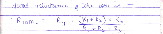
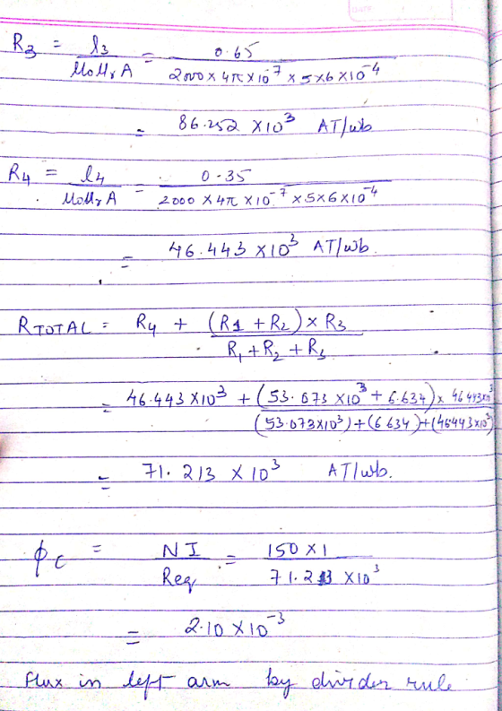
 Magnetic Circuits - Part A - Calculate reluctances Using the information given in the introduction, calculate the reluctances for the equivalent circuit shown. Express your answers to three significant figures in A turns w View Available Hints) 00 AED Ivec ? R. R₂ R- W Learning Goal: To understand how magnetic structures can be analyzed by drawing an equivalent circuit, and to use the equivalent circuit to calculate magnetic fixes and coll currents. When analyzing magnetic structures, the geometry is...
Problem 1) Consider a f r-o 05m with permeability -Kh" 100H1m shown in Figure laAantrof 1+cos)...
 Problem 1) Consider a f r-o 05m with permeability -Kh" 100H1m shown in Figure laAantrof 1+cos) A is injected to coil 1 with N,10 turns a) [5 marks] Draw the equivalent magnetic circuit and determine the values for the magnetomotive force and the reluctances b)(3 marks! Calculate the magnetic fluxes ф..ф, in each section ofthe core. ) [5 marks] Now place coils 2 and 3 with N,-5 and N,-15 turns around the core as shown in figure 1.b. Find current...
Problem (2): owing magnetic circuit, the depth of the core is 5 em, the relative permeability of the the length of the air gap is 1 mm, N, 1000,42A, NA 500, ( 1A, Ns core is 4000, len i the energ...
 Problem (2): owing magnetic circuit, the depth of the core is 5 em, the relative permeability of the the length of the air gap is 1 mm, N, 1000,42A, NA 500, ( 1A, Ns core is 4000, len i the energy density in the air gap is 39788.74, determine i. Ignore fringing effect. Ho 4 x 10⁻⁷ H.m-1. (15 pts) Core: Area A Permeability a A. -5cm N, turns NB NA 50cm
Problem (2): owing magnetic circuit, the depth of...
Problem (2): owing magnetic circuit, the depth of the core is 5 em, the relative permeability of the the length of the air gap is 1 mm, N, 1000,42A, NA 500, ( 1A, Ns core is 4000, len i the energy density in the air gap is 39788.74, determine i. Ignore fringing effect. Ho 4 x 10⁻⁷ H.m-1. (15 pts) Core: Area A Permeability a A. -5cm N, turns NB NA 50cm
Problem (2): owing magnetic circuit, the depth of...
Problem 1 (30 points) The magnetic circuit shown in Fig. 1 is made of casteel with...
 Problem 1 (30 points) The magnetic circuit shown in Fig. 1 is made of casteel with magnetining curve shown 2. The coil A has 350 turns, and the coil Bhas 150 turns. The two coils are connected in series to a voltage source. The depth of the core is 2 cm. Given the dimensions (in cm) as shown in the fie I and to establish a flux density of 0.6 T in the airp. Determine: a. Reluctance of the magnetic...
EO Vuy vvvvvvvv NTurns 93 The relative permeability of the core material is 3500, and the...
 EO Vuy vvvvvvvv NTurns 93 The relative permeability of the core material is 3500, and the average length of the core is 52cm as the cross- section of the core is 64cm2. The core is uniform of cross-section (all limbs have the same cross-section). There are 80 turns on the coil. Answer the following questions, 1) The reluctance of the core (AT/Wb) 2) Find the flux density (T) of the core if the current į in the coil is 0.75...
Electrical circuits Determine: A) Magnetomotive force B) Reluctance C) Current D) What is the air gap...
 Electrical circuits
Determine:
A) Magnetomotive force
B) Reluctance
C) Current
D) What is the air gap flux density, with 3.8% E.M (Marginal
Effect electric machines). ?
Data:
- Magnetic core Permeability μr=4800
- Flow 0.045 WB
E) Draw the equivalent magnetic circuit
Solve step by step
10 cm. 20 cm Cn 15 cm 500 Turns of Wire 15 Cm 400 Turns of Wire 15 cm 0.05 cm Thickness: 3.5cm
Electrical circuits
Determine:
A) Magnetomotive force
B) Reluctance
C) Current
D) What is the air gap flux density, with 3.8% E.M (Marginal
Effect electric machines). ?
Data:
- Magnetic core Permeability μr=4800
- Flow 0.045 WB
E) Draw the equivalent magnetic circuit
Solve step by step
10 cm. 20 cm Cn 15 cm 500 Turns of Wire 15 Cm 400 Turns of Wire 15 cm 0.05 cm Thickness: 3.5cm
Please do all parts Problem 2- Lateral Reluctance Actuator 20 ptsl The actuator shown below has...
 Please do all parts
Problem 2- Lateral Reluctance Actuator 20 ptsl The actuator shown below has a core and movable section of steel. The moveable section is supported by bearings with permeability u o, with Hr. All parts of the actuator extend a depth "a" into the page The rest of the parameters for the actuator N-150 a-5 cm a x a cross section b- 25 cm g 2 cm K-40 Nm Equilibrium position of the steel, xi = 4...
Please do all parts
Problem 2- Lateral Reluctance Actuator 20 ptsl The actuator shown below has a core and movable section of steel. The moveable section is supported by bearings with permeability u o, with Hr. All parts of the actuator extend a depth "a" into the page The rest of the parameters for the actuator N-150 a-5 cm a x a cross section b- 25 cm g 2 cm K-40 Nm Equilibrium position of the steel, xi = 4...
 Problem 1) A ferromagnetic core with relative permeability 1000 has a depth of 5 cm as shown below. All the dimensions are shown in the diagram. Due to fringing effects, the effective area of the air gaps is 10% larger than their physical sizes. a) [10 marks] For i-5 A, draw the equivalent magnetic circuit and determine the flux values for the left, middle, and right arms of the core. b) [3 marks] Now wrap a second coil of 100...
 Magnetic Circuits y Part A - Calculate reluctances Learning Goal: To understand how magnetic structures can be analyzed by drawing an equivalent circuit, and to use the equivalent circuit to calculate magnetic fluxes and coll currents. When analyzing magnetic structures, the geometry is often complex enough that using the fundamental rules can be very difficult without numerical methods. However, there are approximate methods that are often sufficient for engineering calculations. When the magnetic field is mostly contained within cores of...
 ET 103 - ELECTRICAL MACHINES I Assignment 01 QUESTION # 04 A ferromagnetic core with a relative permeability of 1500 is shown in Figure The dimensions are as shown in the diagram, and the depth of the core is 5 cm. The air gaps on the left and right sides of the core are 0.050 and 0.070 cm, respectively. Because of fringing effects, the effective area of the air gaps is 5 percent larger than their physical size. If there...
 Magnetic Circuits - Part A - Calculate reluctances Using the information given in the introduction, calculate the reluctances for the equivalent circuit shown. Express your answers to three significant figures in A turns w View Available Hints) 00 AED Ivec ? R. R₂ R- W Learning Goal: To understand how magnetic structures can be analyzed by drawing an equivalent circuit, and to use the equivalent circuit to calculate magnetic fixes and coll currents. When analyzing magnetic structures, the geometry is...
 Problem 1) Consider a f r-o 05m with permeability -Kh" 100H1m shown in Figure laAantrof 1+cos) A is injected to coil 1 with N,10 turns a) [5 marks] Draw the equivalent magnetic circuit and determine the values for the magnetomotive force and the reluctances b)(3 marks! Calculate the magnetic fluxes ф..ф, in each section ofthe core. ) [5 marks] Now place coils 2 and 3 with N,-5 and N,-15 turns around the core as shown in figure 1.b. Find current...
 Problem (2): owing magnetic circuit, the depth of the core is 5 em, the relative permeability of the the length of the air gap is 1 mm, N, 1000,42A, NA 500, ( 1A, Ns core is 4000, len i the energy density in the air gap is 39788.74, determine i. Ignore fringing effect. Ho 4 x 10⁻⁷ H.m-1. (15 pts) Core: Area A Permeability a A. -5cm N, turns NB NA 50cm
Problem (2): owing magnetic circuit, the depth of...
Problem (2): owing magnetic circuit, the depth of the core is 5 em, the relative permeability of the the length of the air gap is 1 mm, N, 1000,42A, NA 500, ( 1A, Ns core is 4000, len i the energy density in the air gap is 39788.74, determine i. Ignore fringing effect. Ho 4 x 10⁻⁷ H.m-1. (15 pts) Core: Area A Permeability a A. -5cm N, turns NB NA 50cm
Problem (2): owing magnetic circuit, the depth of...
 Problem 1 (30 points) The magnetic circuit shown in Fig. 1 is made of casteel with magnetining curve shown 2. The coil A has 350 turns, and the coil Bhas 150 turns. The two coils are connected in series to a voltage source. The depth of the core is 2 cm. Given the dimensions (in cm) as shown in the fie I and to establish a flux density of 0.6 T in the airp. Determine: a. Reluctance of the magnetic...
 EO Vuy vvvvvvvv NTurns 93 The relative permeability of the core material is 3500, and the average length of the core is 52cm as the cross- section of the core is 64cm2. The core is uniform of cross-section (all limbs have the same cross-section). There are 80 turns on the coil. Answer the following questions, 1) The reluctance of the core (AT/Wb) 2) Find the flux density (T) of the core if the current į in the coil is 0.75...
 Electrical circuits
Determine:
A) Magnetomotive force
B) Reluctance
C) Current
D) What is the air gap flux density, with 3.8% E.M (Marginal
Effect electric machines). ?
Data:
- Magnetic core Permeability μr=4800
- Flow 0.045 WB
E) Draw the equivalent magnetic circuit
Solve step by step
10 cm. 20 cm Cn 15 cm 500 Turns of Wire 15 Cm 400 Turns of Wire 15 cm 0.05 cm Thickness: 3.5cm
Electrical circuits
Determine:
A) Magnetomotive force
B) Reluctance
C) Current
D) What is the air gap flux density, with 3.8% E.M (Marginal
Effect electric machines). ?
Data:
- Magnetic core Permeability μr=4800
- Flow 0.045 WB
E) Draw the equivalent magnetic circuit
Solve step by step
10 cm. 20 cm Cn 15 cm 500 Turns of Wire 15 Cm 400 Turns of Wire 15 cm 0.05 cm Thickness: 3.5cm
 Please do all parts
Problem 2- Lateral Reluctance Actuator 20 ptsl The actuator shown below has a core and movable section of steel. The moveable section is supported by bearings with permeability u o, with Hr. All parts of the actuator extend a depth "a" into the page The rest of the parameters for the actuator N-150 a-5 cm a x a cross section b- 25 cm g 2 cm K-40 Nm Equilibrium position of the steel, xi = 4...
Please do all parts
Problem 2- Lateral Reluctance Actuator 20 ptsl The actuator shown below has a core and movable section of steel. The moveable section is supported by bearings with permeability u o, with Hr. All parts of the actuator extend a depth "a" into the page The rest of the parameters for the actuator N-150 a-5 cm a x a cross section b- 25 cm g 2 cm K-40 Nm Equilibrium position of the steel, xi = 4...
Most questions answered within 3 hours.
-
han discusses the racist practice of badlands, a bar
in the Castro
district of San Francisco,...
asked 3 minutes ago -
A sample of final exam scores is normally distributed with a
mean equal to 25 and...
asked 6 minutes ago -
An investor shorts 100 shares of a stock when the share price is
$50 and closes...
asked 11 minutes ago -
LLOP corporation just paid 4$ dividend per share, you expect the
dividend to grow 8% for...
asked 20 minutes ago -
if we subtract 1000 from 0001 is there overflow? (binary)
asked 28 minutes ago -
Hello, I need help with the function below, The language I am
using is Ocaml
open...
asked 29 minutes ago -
Explain how the presence of glucose represses the gal structural
genes?
asked 37 minutes ago -
For the reaction CaI2+2AgNO3⟶2AgI+Ca(NO3)2 how many grams of
silver iodide, AgI, are produced from 56.5 g...
asked 48 minutes ago -
Write an equation for hydrolysis via acid catalysis.
Using ethyl acetate, ethyl benzoate, ethyl formate or...
asked 56 minutes ago -
Only one graph is needed.
(a) Draw a Supply Curve and the Demand Curve for the...
asked 59 minutes ago -
Fill in the blanks and please show how you arrived at numerical
answers
. The...
asked 59 minutes ago -
91. If the half – life of a sample of radioactive
material is 60 days, what...
asked 1 hour ago