
Homework Answers


Add Answer to:
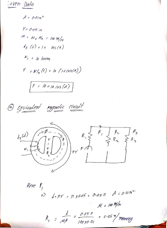
Problem 1) Consider a f r-o 05m with permeability -Kh" 100H1m shown in Figure laAantrof 1+cos)...
Magnetic Circuits y Part A - Calculate reluctances Learning Goal: To understand how magnetic structures can...
 Magnetic Circuits y Part A - Calculate reluctances Learning Goal: To understand how magnetic structures can be analyzed by drawing an equivalent circuit, and to use the equivalent circuit to calculate magnetic fluxes and coll currents. When analyzing magnetic structures, the geometry is often complex enough that using the fundamental rules can be very difficult without numerical methods. However, there are approximate methods that are often sufficient for engineering calculations. When the magnetic field is mostly contained within cores of...
Question 7 A magnetic core is shown in Figure 1. Relative permeability of the core is...
 Question 7 A magnetic core is shown in Figure 1. Relative permeability of the core is 14 = 2000. Total number of winding turns in the left winding is NL = 100 and in the right winding is Nr = 10. Assume that the core cross section is uniform and the combined length of all air-gaps is much smaller than the dimensions of the core cross-section. Calculate the following: a) The magnetomotive force in the core if i = 2...
For problem f), the current value is not on the picture. How to find the force...
 For problem f), the current value is not on the picture. How
to find the force and get the flux without current since F=Ni. Same
for problem g)
5. (34 points) A ferromagnetic core with a constant relative permeability of 2000 is shown in the following figure. The core depth is 6 cm, and all dimensions are as shown in the figure. The air gap length on the leftmost column of the core is 0.01 cm. Because of fringing effects,...
For problem f), the current value is not on the picture. How
to find the force and get the flux without current since F=Ni. Same
for problem g)
5. (34 points) A ferromagnetic core with a constant relative permeability of 2000 is shown in the following figure. The core depth is 6 cm, and all dimensions are as shown in the figure. The air gap length on the leftmost column of the core is 0.01 cm. Because of fringing effects,...
Magnetic Circuits - Part A - Calculate reluctances Using the information given in the introduction, calculate...
 Magnetic Circuits - Part A - Calculate reluctances Using the information given in the introduction, calculate the reluctances for the equivalent circuit shown. Express your answers to three significant figures in A turns w View Available Hints) 00 AED Ivec ? R. R₂ R- W Learning Goal: To understand how magnetic structures can be analyzed by drawing an equivalent circuit, and to use the equivalent circuit to calculate magnetic fixes and coll currents. When analyzing magnetic structures, the geometry is...
Problem 1) A ferromagnetic core with relative permeability 1000 has a depth of 5 cm as...
 Problem 1) A ferromagnetic core with relative permeability 1000 has a depth of 5 cm as shown below. All the dimensions are shown in the diagram. Due to fringing effects, the effective area of the air gaps is 10% larger than their physical sizes. a) [10 marks] For i-5 A, draw the equivalent magnetic circuit and determine the flux values for the left, middle, and right arms of the core. b) [3 marks] Now wrap a second coil of 100...
2.120 pts] A schematic diagram of transformer is shown below. The closed path, l in the magnetic circuit in the Figure is traced by magnetic flux Ф. N,, N2, and 11, 12 are the numbers of turns and th...
 2.120 pts] A schematic diagram of transformer is shown below. The closed path, l in the magnetic circuit in the Figure is traced by magnetic flux Ф. N,, N2, and 11, 12 are the numbers of turns and the currents in the primary and secondary circuits, respectively. The permeability, and cross-section of ferromagnetic core is, u and A İl(r) (a) [6 pts] Draw an equivalent magnetic circuit with two magnetomotive force, Vmmfi, and Vmmf2, magnetic closed flux, 4, and magnetic...
can you calculate this question and explain why? thanks The electromagnet system shown in Figure 1 is used to lift a...
 can you calculate this question and explain why?
thanks
The electromagnet system shown in Figure 1 is used to lift a section of steel channel. The coil has 2000 turns and a resistance of 2 Q. The dimensions of the magnetic system are shown in the figure. The air gap 'g' is 0.5 cm. The reluctances of the electromagnet and channel can be ignored. 4T x10 H/m. 2. The permeability of free space is Find the flux and flux density...
can you calculate this question and explain why?
thanks
The electromagnet system shown in Figure 1 is used to lift a section of steel channel. The coil has 2000 turns and a resistance of 2 Q. The dimensions of the magnetic system are shown in the figure. The air gap 'g' is 0.5 cm. The reluctances of the electromagnet and channel can be ignored. 4T x10 H/m. 2. The permeability of free space is Find the flux and flux density...
a) The transformer shown in Figure B2.1 consists of an infinitely long wire along the z-axis...
 a) The transformer shown in Figure B2.1 consists of an infinitely long wire along the z-axis carrying a current I-cos ot, which couples to an iron toroid centred on the origin (0, 0, 0) and lying in the x-y plane. The iron toroid has a 100 turns coil tightly wound around it which induces a voltage Vemf as shown in Figure B2.1 The permeability of the iron toroid is r, and it has an outer radius of b, inner radius...
Problem 1 (30 points) The magnetic circuit shown in Fig. 1 is made of casteel with...
 Problem 1 (30 points) The magnetic circuit shown in Fig. 1 is made of casteel with magnetining curve shown 2. The coil A has 350 turns, and the coil Bhas 150 turns. The two coils are connected in series to a voltage source. The depth of the core is 2 cm. Given the dimensions (in cm) as shown in the fie I and to establish a flux density of 0.6 T in the airp. Determine: a. Reluctance of the magnetic...
1. (a) The C core and I core as shown in the below figure have a...
 1. (a) The C core and I core as shown in the below figure have a uniform cross-section of 5mm x 5mm. (i) If both cores have a relative permeability ur of 1000, calculate the reluctance when both cores are attached to each other to form a rectangular core. (ii) When a coil of 40 turns is wound around the above rectangular core, calculate the corresponding inductance. (b) The cores described in part (a) are now assembled with a non-magnetic...
 Magnetic Circuits y Part A - Calculate reluctances Learning Goal: To understand how magnetic structures can be analyzed by drawing an equivalent circuit, and to use the equivalent circuit to calculate magnetic fluxes and coll currents. When analyzing magnetic structures, the geometry is often complex enough that using the fundamental rules can be very difficult without numerical methods. However, there are approximate methods that are often sufficient for engineering calculations. When the magnetic field is mostly contained within cores of...
 Question 7 A magnetic core is shown in Figure 1. Relative permeability of the core is 14 = 2000. Total number of winding turns in the left winding is NL = 100 and in the right winding is Nr = 10. Assume that the core cross section is uniform and the combined length of all air-gaps is much smaller than the dimensions of the core cross-section. Calculate the following: a) The magnetomotive force in the core if i = 2...
 For problem f), the current value is not on the picture. How
to find the force and get the flux without current since F=Ni. Same
for problem g)
5. (34 points) A ferromagnetic core with a constant relative permeability of 2000 is shown in the following figure. The core depth is 6 cm, and all dimensions are as shown in the figure. The air gap length on the leftmost column of the core is 0.01 cm. Because of fringing effects,...
For problem f), the current value is not on the picture. How
to find the force and get the flux without current since F=Ni. Same
for problem g)
5. (34 points) A ferromagnetic core with a constant relative permeability of 2000 is shown in the following figure. The core depth is 6 cm, and all dimensions are as shown in the figure. The air gap length on the leftmost column of the core is 0.01 cm. Because of fringing effects,...
 Magnetic Circuits - Part A - Calculate reluctances Using the information given in the introduction, calculate the reluctances for the equivalent circuit shown. Express your answers to three significant figures in A turns w View Available Hints) 00 AED Ivec ? R. R₂ R- W Learning Goal: To understand how magnetic structures can be analyzed by drawing an equivalent circuit, and to use the equivalent circuit to calculate magnetic fixes and coll currents. When analyzing magnetic structures, the geometry is...
 Problem 1) A ferromagnetic core with relative permeability 1000 has a depth of 5 cm as shown below. All the dimensions are shown in the diagram. Due to fringing effects, the effective area of the air gaps is 10% larger than their physical sizes. a) [10 marks] For i-5 A, draw the equivalent magnetic circuit and determine the flux values for the left, middle, and right arms of the core. b) [3 marks] Now wrap a second coil of 100...
 2.120 pts] A schematic diagram of transformer is shown below. The closed path, l in the magnetic circuit in the Figure is traced by magnetic flux Ф. N,, N2, and 11, 12 are the numbers of turns and the currents in the primary and secondary circuits, respectively. The permeability, and cross-section of ferromagnetic core is, u and A İl(r) (a) [6 pts] Draw an equivalent magnetic circuit with two magnetomotive force, Vmmfi, and Vmmf2, magnetic closed flux, 4, and magnetic...
 can you calculate this question and explain why?
thanks
The electromagnet system shown in Figure 1 is used to lift a section of steel channel. The coil has 2000 turns and a resistance of 2 Q. The dimensions of the magnetic system are shown in the figure. The air gap 'g' is 0.5 cm. The reluctances of the electromagnet and channel can be ignored. 4T x10 H/m. 2. The permeability of free space is Find the flux and flux density...
can you calculate this question and explain why?
thanks
The electromagnet system shown in Figure 1 is used to lift a section of steel channel. The coil has 2000 turns and a resistance of 2 Q. The dimensions of the magnetic system are shown in the figure. The air gap 'g' is 0.5 cm. The reluctances of the electromagnet and channel can be ignored. 4T x10 H/m. 2. The permeability of free space is Find the flux and flux density...
 a) The transformer shown in Figure B2.1 consists of an infinitely long wire along the z-axis carrying a current I-cos ot, which couples to an iron toroid centred on the origin (0, 0, 0) and lying in the x-y plane. The iron toroid has a 100 turns coil tightly wound around it which induces a voltage Vemf as shown in Figure B2.1 The permeability of the iron toroid is r, and it has an outer radius of b, inner radius...
 Problem 1 (30 points) The magnetic circuit shown in Fig. 1 is made of casteel with magnetining curve shown 2. The coil A has 350 turns, and the coil Bhas 150 turns. The two coils are connected in series to a voltage source. The depth of the core is 2 cm. Given the dimensions (in cm) as shown in the fie I and to establish a flux density of 0.6 T in the airp. Determine: a. Reluctance of the magnetic...
 1. (a) The C core and I core as shown in the below figure have a uniform cross-section of 5mm x 5mm. (i) If both cores have a relative permeability ur of 1000, calculate the reluctance when both cores are attached to each other to form a rectangular core. (ii) When a coil of 40 turns is wound around the above rectangular core, calculate the corresponding inductance. (b) The cores described in part (a) are now assembled with a non-magnetic...
Most questions answered within 3 hours.
-
Company Risk Premium A company has a beta of
4.57. If the market return is expected...
asked 50 seconds from now -
Arthur Meiners is the production manager of Wheel-Rite, a small
producer of metal parts. Wheel-Rite supplies...
asked 35 seconds ago -
3. Which statement about nuclear fission is correct? (1
point)
A. Nuclear fission provides energy for...
asked 5 minutes ago -
If a $2,000 increase in income leads to a $1,5000 increase in
consumption expenditures, then the...
asked 4 minutes ago -
May you please put this in layman's terms?
ABSTRACT
Coagulase-negative staphylococci (CoNS) and Staphylococcus
aureus are...
asked 9 minutes ago -
If authentic leadership is really a lifelong process,
can teenagers be authentic leaders? Why or why...
asked 25 minutes ago -
Six years of quarterly data of a seasonally adjusted series are
used to estimate a linear...
asked 43 minutes ago -
Which of the following is not an ecological model used
to foster behavior change?
PRECEDE-PROCEED Model...
asked 46 minutes ago -
On the Apollo 14 mission to the moon, astronaut Alan Shepard hit
a golf ball with...
asked 43 minutes ago -
What are John’s potential claims if he is terminated
this week?
John is a 54-year-old man...
asked 56 minutes ago -
A (8.5) cm tall object is placed at a distance of (14.2) cm from
a convex...
asked 1 hour ago -
(2) For the following questions, consider a data set that
exhibits a normal distribution. Report the...
asked 1 hour ago