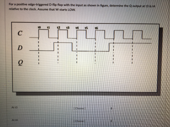
What does t3 and t4 equal? (1 or 0)
Homework Answers
Request Answer!
We need at least 10 more requests to produce the answer.
0 / 10 have requested this problem solution
The more requests, the faster the answer.
Add Answer to:
What does t3 and t4 equal? (1 or 0)
For a positive edge-triggered D flip flop...
All flip flops are positive-edge triggered. Assume each flip flop starts at 0.
 All flip flops are
positive-edge triggered. Assume each flip flop starts at 0.
Problem 11: (8 pts) For the following circuit, complete the timing diagram for the state of each flip flop and the output, where shown. All flip flops are positive-edge triggered. Assume each flip flop starts at 0. J-K FF TFF CLK PRE CLR PRE CLR CLR回 Clock CLR
Problem 11: (8 pts) For the following circuit, complete the timing diagram for the state of each flip flop...
All flip flops are
positive-edge triggered. Assume each flip flop starts at 0.
Problem 11: (8 pts) For the following circuit, complete the timing diagram for the state of each flip flop and the output, where shown. All flip flops are positive-edge triggered. Assume each flip flop starts at 0. J-K FF TFF CLK PRE CLR PRE CLR CLR回 Clock CLR
Problem 11: (8 pts) For the following circuit, complete the timing diagram for the state of each flip flop...
Problem 7.9: The Qoutput of an edge-triggered D flip-flop is shown below in relation to the...
 Problem 7.9: The Qoutput of an edge-triggered D flip-flop is shown below in relation to the clock signal. Determine the input waveform on the D input that is required to produce this output if the flip-flop is a positive edge-triggered type. CLUபுபுப்பப்பட
1. (10) Which of the following describes the operation of a positive edge-triggered D flip-lop? A...
 logic circuit
1. (10) Which of the following describes the operation of a positive edge-triggered D flip-lop? A. If both inputs are HIGH, the output will toggle. B. The output will follow the input on the leading edge of the clock. C. when both inputs are LOW, an invalid state exists. D. The input is toggled into the flip-flop on the leading edge of the clock and is passed to the output on the trailing edge of the clock. Answer...
logic circuit
1. (10) Which of the following describes the operation of a positive edge-triggered D flip-lop? A. If both inputs are HIGH, the output will toggle. B. The output will follow the input on the leading edge of the clock. C. when both inputs are LOW, an invalid state exists. D. The input is toggled into the flip-flop on the leading edge of the clock and is passed to the output on the trailing edge of the clock. Answer...
This is a positive-edge-triggered master-slave D flip-flop. Change this circuit to a negative-edge-triggered master-slave D flip-flop....
 This is a positive-edge-triggered master-slave D flip-flop. Change this circuit to a negative-edge-triggered master-slave D flip-flop. Clock a. <Pre-Lab>Draw the logic circuit.
Question 06: The inputs for a positive edge triggered J-K flip-flop are shown in figure. Find...
 Question 06: The inputs for a positive edge triggered J-K flip-flop are shown in figure. Find the output Q in relative to the CLK signal. Assume that Q is initially RESET. CLK _ பபபபபட PRE V- >
Design a double edge-triggered D flip-flop. The output of the flip-flop Q should "sample" the value...
 Design a double edge-triggered D flip-flop. The output of the flip-flop Q should "sample" the value of the input D on both rising (+ve) and falling (-ve) edges of the clock CLK. Design an FSM counter that counts the sequence: 00, 11, 01, 10,00, 11, ..
Design a double edge-triggered D flip-flop using multiplexers only. The output of the flip-flop Q should...
Design a double edge-triggered D flip-flop using multiplexers only. The output of the flip-flop Q should “sample” the value of the input D on both rising (+ve) and falling (-ve) edges of the clock CLK. Provide detailed solution and explanation.
1. The D Flip-Flop ) Look for the datasheet of the 7474 D flip-flop and wire it on the breadboard...
 1. The D Flip-Flop ) Look for the datasheet of the 7474 D flip-flop and wire it on the breadboard making sure to supply 5V to both Preset and Clear. Utilize the function generator to provide a Clock signal of 1 Hz: i) Press AMPL and set value to 5 Vpp ii) Press FREQ and set value to 1 Hz ili) Press OFFSET and set value to 2.5 V This Clock signal will be the same for all circuits in...
For the T Flip-flop timing diagram below, determine the value of the flip-flop output Q for...
 For the T Flip-flop timing diagram below, determine the value of
the flip-flop output Q for each labeled point in time
(A-H) assuming that Q is zero at time 0
and the clock is positive edge triggered. (Also assume all
setup and hold times are zero.)
For the T Flip-flop timing diagram below, determine the value of the flip-flop output Q for each labeled point in time (A-H) assuming that Q is zero at time 0 and the clock is...
For the T Flip-flop timing diagram below, determine the value of
the flip-flop output Q for each labeled point in time
(A-H) assuming that Q is zero at time 0
and the clock is positive edge triggered. (Also assume all
setup and hold times are zero.)
For the T Flip-flop timing diagram below, determine the value of the flip-flop output Q for each labeled point in time (A-H) assuming that Q is zero at time 0 and the clock is...
5.4 2um 4-34. Design a negative-edge-triggered flip-flop. The flip flop has three inputs; these are Data,...
 5.4 2um
4-34. Design a negative-edge-triggered flip-flop. The flip flop has three inputs; these are Data, Clock, and Enable. If, at the negative edge of the clock, the enable input equals to 0, then the state at Data input is stored in the flip-flop. If, at the negative edge of clock, Enable is in 1 state, then the current stored value in the flip-flop is held. Design the flip-flop using only SR latches, AND gates, and NOT gates.
4-34. Design...
5.4 2um
4-34. Design a negative-edge-triggered flip-flop. The flip flop has three inputs; these are Data, Clock, and Enable. If, at the negative edge of the clock, the enable input equals to 0, then the state at Data input is stored in the flip-flop. If, at the negative edge of clock, Enable is in 1 state, then the current stored value in the flip-flop is held. Design the flip-flop using only SR latches, AND gates, and NOT gates.
4-34. Design...
 All flip flops are
positive-edge triggered. Assume each flip flop starts at 0.
Problem 11: (8 pts) For the following circuit, complete the timing diagram for the state of each flip flop and the output, where shown. All flip flops are positive-edge triggered. Assume each flip flop starts at 0. J-K FF TFF CLK PRE CLR PRE CLR CLR回 Clock CLR
Problem 11: (8 pts) For the following circuit, complete the timing diagram for the state of each flip flop...
All flip flops are
positive-edge triggered. Assume each flip flop starts at 0.
Problem 11: (8 pts) For the following circuit, complete the timing diagram for the state of each flip flop and the output, where shown. All flip flops are positive-edge triggered. Assume each flip flop starts at 0. J-K FF TFF CLK PRE CLR PRE CLR CLR回 Clock CLR
Problem 11: (8 pts) For the following circuit, complete the timing diagram for the state of each flip flop...
 Problem 7.9: The Qoutput of an edge-triggered D flip-flop is shown below in relation to the clock signal. Determine the input waveform on the D input that is required to produce this output if the flip-flop is a positive edge-triggered type. CLUபுபுப்பப்பட
 logic circuit
1. (10) Which of the following describes the operation of a positive edge-triggered D flip-lop? A. If both inputs are HIGH, the output will toggle. B. The output will follow the input on the leading edge of the clock. C. when both inputs are LOW, an invalid state exists. D. The input is toggled into the flip-flop on the leading edge of the clock and is passed to the output on the trailing edge of the clock. Answer...
logic circuit
1. (10) Which of the following describes the operation of a positive edge-triggered D flip-lop? A. If both inputs are HIGH, the output will toggle. B. The output will follow the input on the leading edge of the clock. C. when both inputs are LOW, an invalid state exists. D. The input is toggled into the flip-flop on the leading edge of the clock and is passed to the output on the trailing edge of the clock. Answer...
 This is a positive-edge-triggered master-slave D flip-flop. Change this circuit to a negative-edge-triggered master-slave D flip-flop. Clock a. <Pre-Lab>Draw the logic circuit.
 Question 06: The inputs for a positive edge triggered J-K flip-flop are shown in figure. Find the output Q in relative to the CLK signal. Assume that Q is initially RESET. CLK _ பபபபபட PRE V- >
 Design a double edge-triggered D flip-flop. The output of the flip-flop Q should "sample" the value of the input D on both rising (+ve) and falling (-ve) edges of the clock CLK. Design an FSM counter that counts the sequence: 00, 11, 01, 10,00, 11, ..
 1. The D Flip-Flop ) Look for the datasheet of the 7474 D flip-flop and wire it on the breadboard making sure to supply 5V to both Preset and Clear. Utilize the function generator to provide a Clock signal of 1 Hz: i) Press AMPL and set value to 5 Vpp ii) Press FREQ and set value to 1 Hz ili) Press OFFSET and set value to 2.5 V This Clock signal will be the same for all circuits in...
 For the T Flip-flop timing diagram below, determine the value of
the flip-flop output Q for each labeled point in time
(A-H) assuming that Q is zero at time 0
and the clock is positive edge triggered. (Also assume all
setup and hold times are zero.)
For the T Flip-flop timing diagram below, determine the value of the flip-flop output Q for each labeled point in time (A-H) assuming that Q is zero at time 0 and the clock is...
For the T Flip-flop timing diagram below, determine the value of
the flip-flop output Q for each labeled point in time
(A-H) assuming that Q is zero at time 0
and the clock is positive edge triggered. (Also assume all
setup and hold times are zero.)
For the T Flip-flop timing diagram below, determine the value of the flip-flop output Q for each labeled point in time (A-H) assuming that Q is zero at time 0 and the clock is...
 5.4 2um
4-34. Design a negative-edge-triggered flip-flop. The flip flop has three inputs; these are Data, Clock, and Enable. If, at the negative edge of the clock, the enable input equals to 0, then the state at Data input is stored in the flip-flop. If, at the negative edge of clock, Enable is in 1 state, then the current stored value in the flip-flop is held. Design the flip-flop using only SR latches, AND gates, and NOT gates.
4-34. Design...
5.4 2um
4-34. Design a negative-edge-triggered flip-flop. The flip flop has three inputs; these are Data, Clock, and Enable. If, at the negative edge of the clock, the enable input equals to 0, then the state at Data input is stored in the flip-flop. If, at the negative edge of clock, Enable is in 1 state, then the current stored value in the flip-flop is held. Design the flip-flop using only SR latches, AND gates, and NOT gates.
4-34. Design...
Most questions answered within 3 hours.
-
Executive Program Practical Connection Assignment
Subject : Operations Security.
Assignment:
Provide a reflection of at least...
asked 4 minutes ago -
Every time Casey is at bat he has a 0.4 probability of
getting on base (assume...
asked 13 minutes ago -
The Walston Company is to be liquidated and has the following
liabilities:
Income taxes
$
9,400...
asked 20 minutes ago -
If
the more comprehensive data is available in MEPS, why does the NHIS
still exist? How...
asked 41 minutes ago -
Koo argues that the Japanese economy in the 1990s suffered from
a balance sheet recession. What...
asked 34 minutes ago -
Automobile mechanics conduct diagnosis tests on 150 new cars of
particular make and model to determine...
asked 28 minutes ago -
11) Find the proceeds of a 5 year non-interest
bearing note for $6500 discounted 2.5 years...
asked 35 minutes ago -
Required: Prepare the consolidated financial statements of
Griffin Ltd at 30 June 2019.
Griffin Ltd is...
asked 44 minutes ago -
1.How large must the coefficient of static friction be between
the tires and the road if...
asked 59 minutes ago -
What is the time complexity (Big-O) of the following code?
class Main
{
// Recursive...
asked 59 minutes ago -
Economists look at any situation in terms of its component
parts: the people making decisions, the...
asked 1 hour ago -
What is a population?
Select one:
a. All of the individual organisms belonging to the same...
asked 1 hour ago