
Homework Answers
Add Answer to:
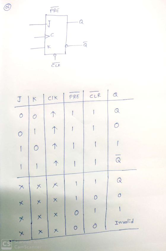
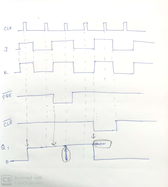
Question 06: The inputs for a positive edge triggered J-K flip-flop are shown in figure. Find...
e Q and Q output waveforms of the flip-flop in Figure 6-18 for the D and...
 e Q and Q output waveforms of the flip-flop in Figure 6-18 for the D and CLK inpusts in Figure 6-19.(a). Assume that the positive edge-triggered flip-flop is initially RESEI CLK 4. For the positive edge-triggered J-K flip-flop with preset and clear inputs in Figure 6-27, determine the Q output for the inputs shown in the timing diagram in part (a) if Q is initially LOW CLK 几几几几几几 PRE PRE CLR CLR 5. Use a K-map to reduce the following...
All flip flops are positive-edge triggered. Assume each flip flop starts at 0.
 All flip flops are
positive-edge triggered. Assume each flip flop starts at 0.
Problem 11: (8 pts) For the following circuit, complete the timing diagram for the state of each flip flop and the output, where shown. All flip flops are positive-edge triggered. Assume each flip flop starts at 0. J-K FF TFF CLK PRE CLR PRE CLR CLR回 Clock CLR
Problem 11: (8 pts) For the following circuit, complete the timing diagram for the state of each flip flop...
All flip flops are
positive-edge triggered. Assume each flip flop starts at 0.
Problem 11: (8 pts) For the following circuit, complete the timing diagram for the state of each flip flop and the output, where shown. All flip flops are positive-edge triggered. Assume each flip flop starts at 0. J-K FF TFF CLK PRE CLR PRE CLR CLR回 Clock CLR
Problem 11: (8 pts) For the following circuit, complete the timing diagram for the state of each flip flop...
For the circuit shown in Figure 7 draw the waveforms Qo and Q1. Note that the J-K flip flop is a negative edge triggered with active LOW and PRESET inputs. Assume Qo and Q1 to be initially 0
 For the circuit shown in Figure 7 draw the waveforms Qo and Q1. Note that the J-K flip flop is a negative edge triggered with active LOW and PRESET inputs. Assume Qo and Q1 to be initially 0
3. Answer the following questions about a data flip-flop (D-Flip Flop): a) (4 ps) Write the VHDL required to define a rising-edge triggered (RET) D-Flip Flop with additional clock enable (CEN) an...
 3. Answer the following questions about a data flip-flop (D-Flip Flop): a) (4 ps) Write the VHDL required to define a rising-edge triggered (RET) D-Flip Flop with additional clock enable (CEN) and reset inputs. Your reset may be synchronous or asynchronous. Assume any input, output, or signal variables that you require have already been declared in VHDL (you do not have to write the declarations for these) b) [I pal ls your reset syachronous or asynchronous for the D-Flip Flop...
What does t3 and t4 equal? (1 or 0) For a positive edge-triggered D flip flop...
 What does t3 and t4 equal? (1 or 0)
For a positive edge-triggered D flip flop with the input as shown in figure, determine the relative to the clock. Assume that W starts LOW. 70 Q output at t4 At t3 At t4
What does t3 and t4 equal? (1 or 0)
For a positive edge-triggered D flip flop with the input as shown in figure, determine the relative to the clock. Assume that W starts LOW. 70 Q output at t4 At t3 At t4
23. A J-K flip-flop has a l on the J input and a 0 on the...
 23. A J-K flip-flop has a l on the J input and a 0 on the K input. What state is the flip-flop in? (a) Q=1,0-0 (b) Q-1, Q-1 (c) Q-0,Q 1 (d) Q-0,Q-0 -24. On a positive edge-triggered S-R flip-flop, the outputs reflect the input condition when (a) the clock pulse is LOW (b) the clock pulse is HIGH (c) the clock pulse transitions from LOW to HIGH (d) the clock pulse transitions from HIGH to LOW 25. The...
Problem 7.9: The Qoutput of an edge-triggered D flip-flop is shown below in relation to the...
 Problem 7.9: The Qoutput of an edge-triggered D flip-flop is shown below in relation to the clock signal. Determine the input waveform on the D input that is required to produce this output if the flip-flop is a positive edge-triggered type. CLUபுபுப்பப்பட
This is a positive-edge-triggered master-slave D flip-flop. Change this circuit to a negative-edge-triggered master-slave D flip-flop....
 This is a positive-edge-triggered master-slave D flip-flop. Change this circuit to a negative-edge-triggered master-slave D flip-flop. Clock a. <Pre-Lab>Draw the logic circuit.
5) Complete the timing diagram for the circuit with one positive-edge and one negative-edge triggered D...
 5) Complete the timing diagram for the circuit with one positive-edge and one negative-edge triggered D FF. Q1 and Q0 start a low (0) because CLRn starts low. CLk K - 1 cun Q ई 6) For each set of waveforms, create a D, T or J/K waveform that will generate the desired Q output. Assume Q starts low. There are several right answers for the J and K inputs. To prevent flip-flop instability, all changes to the D, T...
1. (10) Which of the following describes the operation of a positive edge-triggered D flip-lop? A...
 logic circuit
1. (10) Which of the following describes the operation of a positive edge-triggered D flip-lop? A. If both inputs are HIGH, the output will toggle. B. The output will follow the input on the leading edge of the clock. C. when both inputs are LOW, an invalid state exists. D. The input is toggled into the flip-flop on the leading edge of the clock and is passed to the output on the trailing edge of the clock. Answer...
logic circuit
1. (10) Which of the following describes the operation of a positive edge-triggered D flip-lop? A. If both inputs are HIGH, the output will toggle. B. The output will follow the input on the leading edge of the clock. C. when both inputs are LOW, an invalid state exists. D. The input is toggled into the flip-flop on the leading edge of the clock and is passed to the output on the trailing edge of the clock. Answer...
 e Q and Q output waveforms of the flip-flop in Figure 6-18 for the D and CLK inpusts in Figure 6-19.(a). Assume that the positive edge-triggered flip-flop is initially RESEI CLK 4. For the positive edge-triggered J-K flip-flop with preset and clear inputs in Figure 6-27, determine the Q output for the inputs shown in the timing diagram in part (a) if Q is initially LOW CLK 几几几几几几 PRE PRE CLR CLR 5. Use a K-map to reduce the following...
 All flip flops are
positive-edge triggered. Assume each flip flop starts at 0.
Problem 11: (8 pts) For the following circuit, complete the timing diagram for the state of each flip flop and the output, where shown. All flip flops are positive-edge triggered. Assume each flip flop starts at 0. J-K FF TFF CLK PRE CLR PRE CLR CLR回 Clock CLR
Problem 11: (8 pts) For the following circuit, complete the timing diagram for the state of each flip flop...
All flip flops are
positive-edge triggered. Assume each flip flop starts at 0.
Problem 11: (8 pts) For the following circuit, complete the timing diagram for the state of each flip flop and the output, where shown. All flip flops are positive-edge triggered. Assume each flip flop starts at 0. J-K FF TFF CLK PRE CLR PRE CLR CLR回 Clock CLR
Problem 11: (8 pts) For the following circuit, complete the timing diagram for the state of each flip flop...
 3. Answer the following questions about a data flip-flop (D-Flip Flop): a) (4 ps) Write the VHDL required to define a rising-edge triggered (RET) D-Flip Flop with additional clock enable (CEN) and reset inputs. Your reset may be synchronous or asynchronous. Assume any input, output, or signal variables that you require have already been declared in VHDL (you do not have to write the declarations for these) b) [I pal ls your reset syachronous or asynchronous for the D-Flip Flop...
 What does t3 and t4 equal? (1 or 0)
For a positive edge-triggered D flip flop with the input as shown in figure, determine the relative to the clock. Assume that W starts LOW. 70 Q output at t4 At t3 At t4
What does t3 and t4 equal? (1 or 0)
For a positive edge-triggered D flip flop with the input as shown in figure, determine the relative to the clock. Assume that W starts LOW. 70 Q output at t4 At t3 At t4
 23. A J-K flip-flop has a l on the J input and a 0 on the K input. What state is the flip-flop in? (a) Q=1,0-0 (b) Q-1, Q-1 (c) Q-0,Q 1 (d) Q-0,Q-0 -24. On a positive edge-triggered S-R flip-flop, the outputs reflect the input condition when (a) the clock pulse is LOW (b) the clock pulse is HIGH (c) the clock pulse transitions from LOW to HIGH (d) the clock pulse transitions from HIGH to LOW 25. The...
 Problem 7.9: The Qoutput of an edge-triggered D flip-flop is shown below in relation to the clock signal. Determine the input waveform on the D input that is required to produce this output if the flip-flop is a positive edge-triggered type. CLUபுபுப்பப்பட
 This is a positive-edge-triggered master-slave D flip-flop. Change this circuit to a negative-edge-triggered master-slave D flip-flop. Clock a. <Pre-Lab>Draw the logic circuit.
 5) Complete the timing diagram for the circuit with one positive-edge and one negative-edge triggered D FF. Q1 and Q0 start a low (0) because CLRn starts low. CLk K - 1 cun Q ई 6) For each set of waveforms, create a D, T or J/K waveform that will generate the desired Q output. Assume Q starts low. There are several right answers for the J and K inputs. To prevent flip-flop instability, all changes to the D, T...
 logic circuit
1. (10) Which of the following describes the operation of a positive edge-triggered D flip-lop? A. If both inputs are HIGH, the output will toggle. B. The output will follow the input on the leading edge of the clock. C. when both inputs are LOW, an invalid state exists. D. The input is toggled into the flip-flop on the leading edge of the clock and is passed to the output on the trailing edge of the clock. Answer...
logic circuit
1. (10) Which of the following describes the operation of a positive edge-triggered D flip-lop? A. If both inputs are HIGH, the output will toggle. B. The output will follow the input on the leading edge of the clock. C. when both inputs are LOW, an invalid state exists. D. The input is toggled into the flip-flop on the leading edge of the clock and is passed to the output on the trailing edge of the clock. Answer...
Most questions answered within 3 hours.
-
Please explain steps:
An 80 kg swimmer steps off a platform 10 m above the water...
asked 10 minutes ago -
A lottery exists where balls numbered 1 to 17 are placed in an
urn. To win,...
asked 13 minutes ago -
26) Briefly describe, using words or simple diagrams, the
chemiosmotic theory for coupling oxidation to phosphorylation...
asked 2 hours ago -
Suppose that XX is a random variable with mean 16 and standard
deviation 5 . Also...
asked 2 hours ago -
Calculate the number density of argon gas at a temperature of
24C and a pressure of...
asked 6 hours ago -
Alternative
Classification
How to Estimate
Probabilities from Data? ( For continuous Attributes)
And How to generate...
asked 6 hours ago -
An explosion breaks a 20.0-kg object into three parts. The
object is initially moving at a...
asked 7 hours ago -
Calculate the approximate number of residues of Rubisco, which
is involved in carbon fixation in plants,...
asked 8 hours ago -
Other decisions about scientific claims can have a much broader
impact.ENERGYarrow-10x10.png, environment, health, security - all...
asked 8 hours ago -
I need to write a research paper and work cited about this
topic: The United States...
asked 9 hours ago -
Hello! I was wondering if I could have some help?
If the vapor pressure of carvone...
asked 9 hours ago -
An economist wants to estimate the mean per capita income (in
thousands of dollars) for a...
asked 10 hours ago