Lecture: MicroElectronic Circuits-2
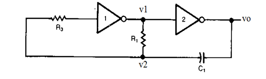
a): Draw V1 , V2 and V0.
b): Find the expression of oscillation frequency.
c): Specify the values of circuit elements to set the oscillation frequency at 100kHz
Homework Answers


Add Answer to:
Lecture: MicroElectronic
Circuits-2
a): Draw V1 , V2 and V0.
b): Find the expression of oscillation...
Consider the following RLC circuit, v1 and v2 are the two inputs and v0 is the...
 Consider the following RLC circuit, v1 and v2 are the two inputs
and v0 is the output.
(a) Obtain the state-space representation for the system if the
state variables are defined as vc and iL.
(b) Draw a signal flow graph based on the state-space model
obtained in (a).
(c) The output can be derived as V0(s) = G1(s)V1(s) +
G2(s)V2(s). Use the state-space model obtained in (a) to find the
transfer fnctions G1(s) and G2(s).
2 0
Consider the following RLC circuit, v1 and v2 are the two inputs
and v0 is the output.
(a) Obtain the state-space representation for the system if the
state variables are defined as vc and iL.
(b) Draw a signal flow graph based on the state-space model
obtained in (a).
(c) The output can be derived as V0(s) = G1(s)V1(s) +
G2(s)V2(s). Use the state-space model obtained in (a) to find the
transfer fnctions G1(s) and G2(s).
2 0
Find the output voltage Vo as an expression in terms of the input sources Vi, v2,...
 Find the output voltage Vo as an expression in terms of the input sources Vi, v2, v3, and the resistance R in the following op-amp circuit. 3. Ri Vy R: 4. In the following two stage op-amp circuit, find the output voltage Vo as an expression in terms of the input voltages v1, v2 and resistor values R1, R2, R3, and R4. R2 R ウー+
Data Converters and Timing Circuits (20 marks) (a) For the timing circuit shown below, use a 1000pF capacitor and find the values of RA and RB that result in an oscillation frequency of 100KHz an...
 Data Converters and Timing Circuits (20 marks) (a) For the timing circuit shown below, use a 1000pF capacitor and find the values of RA and RB that result in an oscillation frequency of 100KHz and a duty cycle of 75% Reset 0.693 R,+2R,)C Discharge Outpat Threshold Trigger Ground Duty-Cle2R R,+2R, ar (b) The 4-Bit Weighted-Resistor DAC Converter shown below is to be expanded into an 8-bit device a. What are the required values of the additional resistors to be added?...
b. Determine the symbolic expression for Vo2/V2 (Vo2: output voltage contributed by V2 when V1 =...
 b. Determine the symbolic expression for Vo2/V2 (Vo2: output
voltage contributed by V2 when V1 = 0).
c Determine the symbolic expression for Vo in terms of V1 and V2
using superposition.
d. This circuit is (circle two):
Non-inverting amp / Inverting amp / subtractor / adder
R1 R3 (4) (22%) Consider the op-amp circuit shown to the right. Assume the op-amp is ideal and operating in the linear range. Answer the following questions. M3 MV + (a) (7%) Determine...
b. Determine the symbolic expression for Vo2/V2 (Vo2: output
voltage contributed by V2 when V1 = 0).
c Determine the symbolic expression for Vo in terms of V1 and V2
using superposition.
d. This circuit is (circle two):
Non-inverting amp / Inverting amp / subtractor / adder
R1 R3 (4) (22%) Consider the op-amp circuit shown to the right. Assume the op-amp is ideal and operating in the linear range. Answer the following questions. M3 MV + (a) (7%) Determine...
EXERCISE 12.2 For each of the circuits in Figure 12.66, find and sketch the indicated zero-input response corresponding to the indicated initial conditions a) In Figure 12.66, find v2, assuming v1(01...
 EXERCISE 12.2 For each of the circuits in Figure 12.66, find and sketch the indicated zero-input response corresponding to the indicated initial conditions a) In Figure 12.66, find v2, assuming v1(01 V, v2(00 b) In Figure 12.67, find v, assuming i(0) 0, v0) 1V c) Repeat (b), but with the resistor changed to 5 S2 i mH 10 uF 10022 V 24 FIGURE 12.67 FIGURE 12.66
EXERCISE 12.2 For each of the circuits in Figure 12.66, find and sketch the...
EXERCISE 12.2 For each of the circuits in Figure 12.66, find and sketch the indicated zero-input response corresponding to the indicated initial conditions a) In Figure 12.66, find v2, assuming v1(01 V, v2(00 b) In Figure 12.67, find v, assuming i(0) 0, v0) 1V c) Repeat (b), but with the resistor changed to 5 S2 i mH 10 uF 10022 V 24 FIGURE 12.67 FIGURE 12.66
EXERCISE 12.2 For each of the circuits in Figure 12.66, find and sketch the...
your name here and on the back: In the given circuit 11-10mA, B- po 100, V2-15V...
 your name here and on the back: In the given circuit 11-10mA, B- po 100, V2-15V and the capacitors are very large a) (2) Find lco b) (2) Find Vcro c) (2) Draw the AC midband model for the circuit C1 V2 CEO- R2 showing all component values. d) (2) What is the voltage gain of this amplifier? e (2) What load does VI see? V1 C2 0
2) RLC series circuits R1 1m 2 1E-6 V1 C1 1E-12 TR = Ở TF 0...
 2) RLC series circuits R1 1m 2 1E-6 V1 C1 1E-12 TR = Ở TF 0 PW = 1 PER = 2 In the above circuit, the voltage source is 5V for t<0 and 10V for t>0 2.1: Draw the s-domain equivalent circuit. Include the intial conditions in your s-domain circuit. Label your component values using symbolic notation (eg. sL1). 2.2: Using impedances, determine the transfer function for the voltage across C1. Use symbolic numbers in your expression. 2.3: Using...
In the circuit below, the input voltage is Vin-Vinegakcos(wt), R-20 ΚΩandC15nFw l. in al Show that the output voltage is VotVcos (wt-), where V-V n peak/V1 + (RC) b) Show that this result justifies c...
 In the circuit below, the input voltage is Vin-Vinegakcos(wt), R-20 ΚΩandC15nFw l. in al Show that the output voltage is VotVcos (wt-), where V-V n peak/V1 + (RC) b) Show that this result justifies calling this circuit a high-pass filter+ c) Find an expression for the phase constant δ in terms of R,C and d) At what frequency is Vi (1/V2) Vin peak? That particular frequency is known as the 3dB frequency, or f3dB, of the circuit
In the circuit...
In the circuit below, the input voltage is Vin-Vinegakcos(wt), R-20 ΚΩandC15nFw l. in al Show that the output voltage is VotVcos (wt-), where V-V n peak/V1 + (RC) b) Show that this result justifies calling this circuit a high-pass filter+ c) Find an expression for the phase constant δ in terms of R,C and d) At what frequency is Vi (1/V2) Vin peak? That particular frequency is known as the 3dB frequency, or f3dB, of the circuit
In the circuit...
2.34. Consider the common-emitter amplifier on the right. (a)Draw a small-signal equivalent circuit using the T-model without the B1 Cci output resistance (b)Find an expression for the input resistan...
 2.34. Consider the common-emitter amplifier on the right. (a)Draw a small-signal equivalent circuit using the T-model without the B1 Cci output resistance (b)Find an expression for the input resistance Rin. (c)Find an expression for the output resistance Ro. (d) Find an expression for the lower cut-off frequency Vi Re sig 82 C, (RE-R) in associated with Cci. (d)Find expressions for the two gains vo/v, and v/Vsig CI.
2.34. Consider the common-emitter amplifier on the right. (a)Draw a small-signal equivalent circuit...
2.34. Consider the common-emitter amplifier on the right. (a)Draw a small-signal equivalent circuit using the T-model without the B1 Cci output resistance (b)Find an expression for the input resistance Rin. (c)Find an expression for the output resistance Ro. (d) Find an expression for the lower cut-off frequency Vi Re sig 82 C, (RE-R) in associated with Cci. (d)Find expressions for the two gains vo/v, and v/Vsig CI.
2.34. Consider the common-emitter amplifier on the right. (a)Draw a small-signal equivalent circuit...
Practice Problems- Basic circuits- (MENG3531) 1. For a low-pass filter with R=1k and C=0.01uF, find time...
 Practice Problems- Basic circuits- (MENG3531) 1. For a low-pass filter with R=1k and C=0.01uF, find time constant (t), rise time (tr), corner frequency (@c) and bandwidth. Sketch time and frequency response curves for the RC circuit and show the calculated parameters. 2. If the Ris changed to 10 k and C is reduced to 0.005 uF, find the corresponding values of time constant (T), rise time (tr), corner frequency (oc). Sketch time and frequency response curves for the RC circuit...
 Consider the following RLC circuit, v1 and v2 are the two inputs
and v0 is the output.
(a) Obtain the state-space representation for the system if the
state variables are defined as vc and iL.
(b) Draw a signal flow graph based on the state-space model
obtained in (a).
(c) The output can be derived as V0(s) = G1(s)V1(s) +
G2(s)V2(s). Use the state-space model obtained in (a) to find the
transfer fnctions G1(s) and G2(s).
2 0
Consider the following RLC circuit, v1 and v2 are the two inputs
and v0 is the output.
(a) Obtain the state-space representation for the system if the
state variables are defined as vc and iL.
(b) Draw a signal flow graph based on the state-space model
obtained in (a).
(c) The output can be derived as V0(s) = G1(s)V1(s) +
G2(s)V2(s). Use the state-space model obtained in (a) to find the
transfer fnctions G1(s) and G2(s).
2 0
 Find the output voltage Vo as an expression in terms of the input sources Vi, v2, v3, and the resistance R in the following op-amp circuit. 3. Ri Vy R: 4. In the following two stage op-amp circuit, find the output voltage Vo as an expression in terms of the input voltages v1, v2 and resistor values R1, R2, R3, and R4. R2 R ウー+
 Data Converters and Timing Circuits (20 marks) (a) For the timing circuit shown below, use a 1000pF capacitor and find the values of RA and RB that result in an oscillation frequency of 100KHz and a duty cycle of 75% Reset 0.693 R,+2R,)C Discharge Outpat Threshold Trigger Ground Duty-Cle2R R,+2R, ar (b) The 4-Bit Weighted-Resistor DAC Converter shown below is to be expanded into an 8-bit device a. What are the required values of the additional resistors to be added?...
 b. Determine the symbolic expression for Vo2/V2 (Vo2: output
voltage contributed by V2 when V1 = 0).
c Determine the symbolic expression for Vo in terms of V1 and V2
using superposition.
d. This circuit is (circle two):
Non-inverting amp / Inverting amp / subtractor / adder
R1 R3 (4) (22%) Consider the op-amp circuit shown to the right. Assume the op-amp is ideal and operating in the linear range. Answer the following questions. M3 MV + (a) (7%) Determine...
b. Determine the symbolic expression for Vo2/V2 (Vo2: output
voltage contributed by V2 when V1 = 0).
c Determine the symbolic expression for Vo in terms of V1 and V2
using superposition.
d. This circuit is (circle two):
Non-inverting amp / Inverting amp / subtractor / adder
R1 R3 (4) (22%) Consider the op-amp circuit shown to the right. Assume the op-amp is ideal and operating in the linear range. Answer the following questions. M3 MV + (a) (7%) Determine...
 EXERCISE 12.2 For each of the circuits in Figure 12.66, find and sketch the indicated zero-input response corresponding to the indicated initial conditions a) In Figure 12.66, find v2, assuming v1(01 V, v2(00 b) In Figure 12.67, find v, assuming i(0) 0, v0) 1V c) Repeat (b), but with the resistor changed to 5 S2 i mH 10 uF 10022 V 24 FIGURE 12.67 FIGURE 12.66
EXERCISE 12.2 For each of the circuits in Figure 12.66, find and sketch the...
EXERCISE 12.2 For each of the circuits in Figure 12.66, find and sketch the indicated zero-input response corresponding to the indicated initial conditions a) In Figure 12.66, find v2, assuming v1(01 V, v2(00 b) In Figure 12.67, find v, assuming i(0) 0, v0) 1V c) Repeat (b), but with the resistor changed to 5 S2 i mH 10 uF 10022 V 24 FIGURE 12.67 FIGURE 12.66
EXERCISE 12.2 For each of the circuits in Figure 12.66, find and sketch the...
 your name here and on the back: In the given circuit 11-10mA, B- po 100, V2-15V and the capacitors are very large a) (2) Find lco b) (2) Find Vcro c) (2) Draw the AC midband model for the circuit C1 V2 CEO- R2 showing all component values. d) (2) What is the voltage gain of this amplifier? e (2) What load does VI see? V1 C2 0
 2) RLC series circuits R1 1m 2 1E-6 V1 C1 1E-12 TR = Ở TF 0 PW = 1 PER = 2 In the above circuit, the voltage source is 5V for t<0 and 10V for t>0 2.1: Draw the s-domain equivalent circuit. Include the intial conditions in your s-domain circuit. Label your component values using symbolic notation (eg. sL1). 2.2: Using impedances, determine the transfer function for the voltage across C1. Use symbolic numbers in your expression. 2.3: Using...
 In the circuit below, the input voltage is Vin-Vinegakcos(wt), R-20 ΚΩandC15nFw l. in al Show that the output voltage is VotVcos (wt-), where V-V n peak/V1 + (RC) b) Show that this result justifies calling this circuit a high-pass filter+ c) Find an expression for the phase constant δ in terms of R,C and d) At what frequency is Vi (1/V2) Vin peak? That particular frequency is known as the 3dB frequency, or f3dB, of the circuit
In the circuit...
In the circuit below, the input voltage is Vin-Vinegakcos(wt), R-20 ΚΩandC15nFw l. in al Show that the output voltage is VotVcos (wt-), where V-V n peak/V1 + (RC) b) Show that this result justifies calling this circuit a high-pass filter+ c) Find an expression for the phase constant δ in terms of R,C and d) At what frequency is Vi (1/V2) Vin peak? That particular frequency is known as the 3dB frequency, or f3dB, of the circuit
In the circuit...
 2.34. Consider the common-emitter amplifier on the right. (a)Draw a small-signal equivalent circuit using the T-model without the B1 Cci output resistance (b)Find an expression for the input resistance Rin. (c)Find an expression for the output resistance Ro. (d) Find an expression for the lower cut-off frequency Vi Re sig 82 C, (RE-R) in associated with Cci. (d)Find expressions for the two gains vo/v, and v/Vsig CI.
2.34. Consider the common-emitter amplifier on the right. (a)Draw a small-signal equivalent circuit...
2.34. Consider the common-emitter amplifier on the right. (a)Draw a small-signal equivalent circuit using the T-model without the B1 Cci output resistance (b)Find an expression for the input resistance Rin. (c)Find an expression for the output resistance Ro. (d) Find an expression for the lower cut-off frequency Vi Re sig 82 C, (RE-R) in associated with Cci. (d)Find expressions for the two gains vo/v, and v/Vsig CI.
2.34. Consider the common-emitter amplifier on the right. (a)Draw a small-signal equivalent circuit...
 Practice Problems- Basic circuits- (MENG3531) 1. For a low-pass filter with R=1k and C=0.01uF, find time constant (t), rise time (tr), corner frequency (@c) and bandwidth. Sketch time and frequency response curves for the RC circuit and show the calculated parameters. 2. If the Ris changed to 10 k and C is reduced to 0.005 uF, find the corresponding values of time constant (T), rise time (tr), corner frequency (oc). Sketch time and frequency response curves for the RC circuit...
Most questions answered within 3 hours.
-
Computer Programming II CS141(Java)
Mention the appropriate relationship between following
classes:
HOD–StaffMember
Car–Ferrari
Student-Address
BankAccount–FixedAccount
House-Building...
asked 2 hours ago -
Assume one of your finals has 50 questions on it, and
lucky for you, it's all...
asked 3 hours ago -
Rice Products in Bangladesh
Business behavior is derived in large part from the basic cultural
environment...
asked 4 hours ago -
The following base sequence is found for a mRNA fragment from
wild-type E. coli: 5'- UAUCAGUAGAUAAUGUAACC-3'...
asked 5 hours ago -
For this exercise, round all regression parameters to three
decimal places.
One of the two tables...
asked 5 hours ago -
What is the 5% level of significance for mean = 3.60, standard
deviation = 0.94, and...
asked 5 hours ago -
Prior to beginning work on this discussion, please read the
article by Hayley Peterson, 15 Companies...
asked 5 hours ago -
Which pair of aqueous solutions, when mixed, will form a
precipitate?
A) NaNO3 and AgC2H3O2
B)...
asked 6 hours ago -
1-Write an algorithm to get two numbers from the user (as
inputs) and calculate the sum...
asked 9 hours ago -
Define white-collar crime. What is the difference between
offender and offense-based definitions of white-collar crime? What...
asked 10 hours ago -
Consider a reaction which is 1st order with respect to A and 1st
order with respect...
asked 10 hours ago -
c++
The length of the hypotenuse of a right-angled triangle is the
square root of the...
asked 10 hours ago