
Homework Answers
The detailed step-by-step calculations for the given problem is described in the images below:


Add Answer to:
static and material strength
Problem 4- The Fig. below shows a shaft carrying a pulley A...
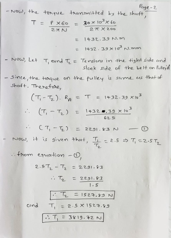
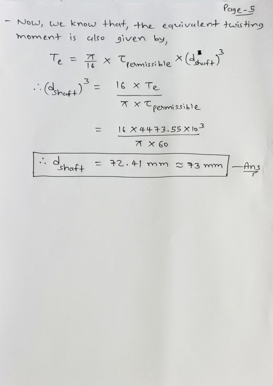
The layout of a shaft carrying two pulleys 1 and 2, and supported on two bearings A and B is shown in Figure 2.2
 Q2 (b) The layout of a shaft carrying two pulleys 1 and 2, and supported on two bearings A and B is shown in Figure 2.2. The shaft transmits 7.5 kW power at 360 rpm from pulley 1 to pulley 2. The diameters of pulley 1 and 2 are 250 mm and 500 mm respectively. The masses of pulley 1 and 2 are 10 kg and 30 kg respectively. The belt tensions act vertically downward and ratio of the belt...
A 24 inch diameter pulley driven by a horizontal belt transmits power (20 marks) (a) through...
 A 24 inch diameter pulley driven by a horizontal belt transmits power (20 marks) (a) through a solid shaft to a 10 inch diameter pinion which drives a mating gear. The pulley weighs 300 lb to provide some fly wheel effect. The arrangement of elements, the belt tensions, and the components of the gear reactions on the pinion are as indicated in figure-3. Determine the necessary shaft diameter using ASME Code stress value for commercial shafting and shock fatigue factors...
A transmission shaft is supported on two bearings which are 1m apart. Power is supplied to the shaft by means of a flexible coupling, which is located to the left of left hand bearing. Power is transmitted from the shaft by means of a belt pulley, 250 mm
A transmission shaft is supported on two bearings which are 1m apart. Power is supplied to the shaft by means of a flexible coupling, which is located to the left of left hand bearing. Power is transmitted from the shaft by means of a belt pulley, 250 mm diameter, which is located at a distance of 300 mm from the left hand bearing. The mass of the pulley is 20 kg and the ratio of belt tension on tight and slack sides is 2:1. The...
Problem 1 (a) (200 points) Shaft fatigue strength In the figure below, a rotating shaft (for...
 Problem 1 (a) (200 points) Shaft fatigue strength In the figure below, a rotating shaft (for speed reducing gearbox) is subjected to radial forces at A-400 lbrand at C-800 iht. These radial forces are caused by spur gears mounted to shar (a result of the pressure angle of the teeth, 20 degrees) that mesh with 2 other spur gears, not shown. Also, The shaft transmits a constant torque of 11110 in-Ibr (925 - due to the tangential force (s: transmitted...
Problem 1 (50 points) A countershaft carrying two V-belt pulleys is shown in the figure. Pulley...
 Problem 1 (50 points) A countershaft carrying two V-belt pulleys is shown in the figure. Pulley A receives power from a motor through a belt with tensions shown. The power is transmitted through the shaft and delivered to the belt on pulley B. Assume the belt tension on the loose side at B is 15 percent of the tension on the tight side. 230 mm F: 30-mm dia. 280 mm 300 mm 250-mm dia. 400-mm dia 1000 N 150 N...
In the figure below, a rotating shaft (for speed reducing gearbox) is subjected to radial forces at A= 400 lbr
 In the figure below, a rotating shaft (for speed reducing gearbox) is subjected to radial forces at A= 400 lbr .and at C = 800 Ibr. These radial forces are caused by spur gears mounted to shaft (a result of the pressure angle of the teeth, 20 degrees) that mesh with 2 other spur gears, not shown. Also, The shaft transmits a constant torque of 11110 in-lbr (925 ft-lbr) due to the tangential force (Wt: transmitted load) at C of...
2.The shaft shown in the figure is driven by a gear at the right keyways, drive...
 2.The shaft shown in the figure is driven by a gear at the right keyways, drive a fan at eh left keyways, and supported by two deep grove ball bearings. The shaft is made of AISI 1020 cold- drawn steel. At steady state speed, the gear transmits a radial load of 230 Ibf and a tangential load of 633 Ibf at pitch diameter of 8 inch. Determine fatigue factor of safety at any potentially critical locations using the DE-Gerber failure...
Figure 1 shows the layout of countershaft used to transmit power to a blower through a...
 Figure 1 shows the layout of countershaft used to transmit power to a blower through a pulley drive (4-5). Pulley (driving sheave) 4 has a diameter of 125-mm and pulley (driven sheave) 5 has a diameter of 75 mm. Pulley 5 is mounted vertically below pulley 4 (as shown in the figure). Belt tension on the loose side is 20% of the tension on the tight side. A power of 7.5 kW is transmitted via the gear set (2-3) from...
 A 24 inch diameter pulley driven by a horizontal belt transmits power (20 marks) (a) through a solid shaft to a 10 inch diameter pinion which drives a mating gear. The pulley weighs 300 lb to provide some fly wheel effect. The arrangement of elements, the belt tensions, and the components of the gear reactions on the pinion are as indicated in figure-3. Determine the necessary shaft diameter using ASME Code stress value for commercial shafting and shock fatigue factors...
 Problem 1 (a) (200 points) Shaft fatigue strength In the figure below, a rotating shaft (for speed reducing gearbox) is subjected to radial forces at A-400 lbrand at C-800 iht. These radial forces are caused by spur gears mounted to shar (a result of the pressure angle of the teeth, 20 degrees) that mesh with 2 other spur gears, not shown. Also, The shaft transmits a constant torque of 11110 in-Ibr (925 - due to the tangential force (s: transmitted...
 Problem 1 (50 points) A countershaft carrying two V-belt pulleys is shown in the figure. Pulley A receives power from a motor through a belt with tensions shown. The power is transmitted through the shaft and delivered to the belt on pulley B. Assume the belt tension on the loose side at B is 15 percent of the tension on the tight side. 230 mm F: 30-mm dia. 280 mm 300 mm 250-mm dia. 400-mm dia 1000 N 150 N...
 2.The shaft shown in the figure is driven by a gear at the right keyways, drive a fan at eh left keyways, and supported by two deep grove ball bearings. The shaft is made of AISI 1020 cold- drawn steel. At steady state speed, the gear transmits a radial load of 230 Ibf and a tangential load of 633 Ibf at pitch diameter of 8 inch. Determine fatigue factor of safety at any potentially critical locations using the DE-Gerber failure...
 Figure 1 shows the layout of countershaft used to transmit power to a blower through a pulley drive (4-5). Pulley (driving sheave) 4 has a diameter of 125-mm and pulley (driven sheave) 5 has a diameter of 75 mm. Pulley 5 is mounted vertically below pulley 4 (as shown in the figure). Belt tension on the loose side is 20% of the tension on the tight side. A power of 7.5 kW is transmitted via the gear set (2-3) from...
Most questions answered within 3 hours.
-
A gas occupies 200. mL in a piston. If the pressure of the
piston were decreased...
asked 1 minute ago -
A fossil is found to have a 14C level of 71.0% compared to
living organisms. How...
asked 5 minutes ago -
Many communist or socialist countries have a department that
addresses public health as well as the...
asked 6 minutes ago -
the following questions are either true or false answers
1. The Central Limit Theorem allows one...
asked 7 minutes ago -
The patient recovery time from a particular surgical procedure
is normally distributed with a mean of...
asked 13 minutes ago -
Human relations refer to the way a company arranges people,
jobs, and communications so that work...
asked 30 minutes ago -
Python Program: Design the logic for and implement a program
that merges the two files into...
asked 28 minutes ago -
The specific radiocarbon activity of a sample of wood is 6.25
gms dpm/gm of carbon. The...
asked 33 minutes ago -
An aqueous magnesium chloride solution is made by dissolving
6.96 moles of MgCl2 in sufficient water...
asked 36 minutes ago -
Ken believes the average age of men who come to get a haircut at
his barber...
asked 58 minutes ago -
(Ratio Analysis): Last year Co. XYZ had sales of $ 400,000, with
“cost of goods sold”...
asked 1 hour ago -
can someone please write the balanced chemical
equation for the synthesis of Bromoacetanilide
from;
aniline +...
asked 1 hour ago