
Homework Answers


 MatLab
Code:
MatLab
Code:
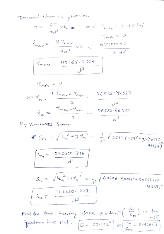
% Good man equation 17817.87*sm + 161000*sa=1434338535
%So here we have two points when sa=0, sm= 80500 and when sm=0,
sa=8908.935
x1= 80500; x2=0;y1=0;y2=8908.935;
%Modified goodman line, for this let the line length be 8000 and
theta=
%23.102 degree=0.4032 rad
L=500000;
theta = 0.4032;
x=0;y=0; % origin
x3= x+ (L*cos(theta));
y3= y+ (L*sin(theta));
figure;hold on;
line([x1,y1],[x2,y2],'Color','g','LineWidth',1.5);
line([x,x3],[y,y3],'Color','r','LineWidth',1.5);
xlabel('Mean Stress (S_m)','FontSize',20);
ylabel('Stress Amplitude(S_a)','FontSize',20);
title('Goodman Line and Modified goodman
line','FontSize',20);
set(gca,'FontSize',20);
xlim([0 200000]);
ylim([0 10000]);
grid on;
hold off;
Output:

Add Answer to:
Problem 1 (a) (200 points) Shaft fatigue strength In the figure below, a rotating shaft (for...
In the figure below, a rotating shaft (for speed reducing gearbox) is subjected to radial forces at A= 400 lbr
 In the figure below, a rotating shaft (for speed reducing gearbox) is subjected to radial forces at A= 400 lbr .and at C = 800 Ibr. These radial forces are caused by spur gears mounted to shaft (a result of the pressure angle of the teeth, 20 degrees) that mesh with 2 other spur gears, not shown. Also, The shaft transmits a constant torque of 11110 in-lbr (925 ft-lbr) due to the tangential force (Wt: transmitted load) at C of...
7-25 A shaft is to be designed to support the spur pinion and helical gear shown in the figure on two bearings spaced 700 mm center-to-center. Bearing A is a cylindrical roller and is to take onl...
 7-25 A shaft is to be designed to support the spur pinion and helical gear shown in the figure on two bearings spaced 700 mm center-to-center. Bearing A is a cylindrical roller and is to take only radial load; bearingB is to take the thrust load of 900 N produced by the helical gear and its share of the radial load. The bearing at B can be a bal bearing. The radial loads of both gears are in the same...
can you please explain how to calculate the axial load for each gear and supporting load for each bearing? thank you! Task 1: A shaft is to be designed to support the spur pinion and helical gea...
 can you please explain how to calculate the axial load for
each gear and supporting load for each bearing? thank you!
Task 1: A shaft is to be designed to support the spur pinion and helical gear shown in the figure below on two bearings spaced 700 mm center-to-center. Bearing A is a cylindrical roller bearing and has to take only radial load; bearing B has to take the thrust load produced by the helical gear and its share of...
can you please explain how to calculate the axial load for
each gear and supporting load for each bearing? thank you!
Task 1: A shaft is to be designed to support the spur pinion and helical gear shown in the figure below on two bearings spaced 700 mm center-to-center. Bearing A is a cylindrical roller bearing and has to take only radial load; bearing B has to take the thrust load produced by the helical gear and its share of...
Is the factor of safety guarding against damaging distortion? What is the factor of safety guard-...
 is the factor of safety guarding against damaging distortion? What is the factor of safety guard- ing against a fatigue failure? If the shaft turns out to be unsatisfactory, what would you rec- ommend to correct the problem? A shaft is to be designed to support the spur pinion and helical gear shown in th two bearings spaced 28 in center-to-center. Bearing A is a cylindrical roller and is to take only radial load; bearing B is to take the...
The shaft shown in the figure is machined from AISI 1040 CD steel and is supported in rolling bearings at A and B.
 The shaft shown in the figure is machined from AISI 1040 CD steel and is supported in rolling bearings at A and B. The applied forces F1 = 1500 lbf and F2 = 3000 lbf are coming off of gears located at respective positions. The shaft rotates at 2000 rpm while transmitting 50hp between the gears. Determine the minimum fatigue factor of safety based on achieving infinite life using Modified- Goodman theory. If infinite life is not predicted, estimate the...
1) The shaft shown in the figure is machined from AISI 1040 CD steel. The shaft...
 1) The shaft shown in the figure is machined from AISI 1040 CD steel. The shaft rotates at 1600 rpm and is supported in rolling bearings at A and B. The applied forces are F1-1000 lbf and F2-400 lbf. The torque, 100 lbf.in, is also applied between C and D. Determine the minimum fatigue factor of safety based on: a) Soderburg b) Modified-Goodman c) Gerber d) ASME-DE (ASME-DE criteria e) If infinite life is not predicted, estimate the number of...
A rotating shaft is made of AISI 1035 CD steel is subjected to an axial load of 710N
 A rotating shaft is made of AISI 1035 CD steel is subjected to an axial load of 710N, a fluctuating torque load from 60 to 120 N.m, and a completely reversed bending moment of 160N.m. The shaft has a diameter of 30mm, and operates at T=250°C, and has a life reliability of 95%. Note that the fatigue stress-concentration factor for bending Kfb is 1.49 and that for torque Kft is 2.65..1. Draw the Yield (Langer) line 2. Modified Goodman line. 3. Calculate...
Question 2: [20 Points) The Figure below shows a portion of a pump that is gear...
 Question 2: [20 Points) The Figure below shows a portion of a pump that is gear driven at uniform load and speed. The shaft is supported by bearings mounted in the pump housing. The shaft is made of steel, its yield strength is 800 MPa and its ultimate tensile strength is 1000 MPa. The surface of the shaft is machined. Due to the fillet at A, the fatigue bending stress concentration factor is 2.0, the fatigue torsion stress concentration factor...
1) Determine unmodified fatigue strength (units = MPa) of hot-rolled 1020 steel shaft in axial loading...
1) Determine unmodified fatigue strength (units = MPa) of hot-rolled 1020 steel shaft in axial loading for a design life of 100,000 cycles. Do not apply any fatigue correction factors. SN _______________ 2) Determine unmodified fatigue strength (units = ksi) for a normalized 4140 steel shaft in bending for a design life of 107 cycles. Do not apply any fatigue correction factors. SN _______________ 3) Determine unmodified fatigue strength (units = MPa) for heat-treated 6061 aluminum rod in torsion for...
A transfer shaft with two spur gears shown below: Input Gear 1 Output Gear Torque Bearing...
 A transfer shaft with two spur gears shown below: Input Gear 1 Output Gear Torque Bearing 1 Gear 1 Gear 2 Bearing 2 B OTO 4" 4" 4" 4 . . Weight Ibf Teeth number Pressure angle Po (diametric pitch) teeth/in Gear A 50 20° 6 Gear C 2 25 20° 6 Deep groove ball bearings at B and D. Pitch diameter of the gear is equal to the teeth number divided by diametric pitch. Shaft speed = 3000 rpm....
 7-25 A shaft is to be designed to support the spur pinion and helical gear shown in the figure on two bearings spaced 700 mm center-to-center. Bearing A is a cylindrical roller and is to take only radial load; bearingB is to take the thrust load of 900 N produced by the helical gear and its share of the radial load. The bearing at B can be a bal bearing. The radial loads of both gears are in the same...
 can you please explain how to calculate the axial load for
each gear and supporting load for each bearing? thank you!
Task 1: A shaft is to be designed to support the spur pinion and helical gear shown in the figure below on two bearings spaced 700 mm center-to-center. Bearing A is a cylindrical roller bearing and has to take only radial load; bearing B has to take the thrust load produced by the helical gear and its share of...
can you please explain how to calculate the axial load for
each gear and supporting load for each bearing? thank you!
Task 1: A shaft is to be designed to support the spur pinion and helical gear shown in the figure below on two bearings spaced 700 mm center-to-center. Bearing A is a cylindrical roller bearing and has to take only radial load; bearing B has to take the thrust load produced by the helical gear and its share of...
 is the factor of safety guarding against damaging distortion? What is the factor of safety guard- ing against a fatigue failure? If the shaft turns out to be unsatisfactory, what would you rec- ommend to correct the problem? A shaft is to be designed to support the spur pinion and helical gear shown in th two bearings spaced 28 in center-to-center. Bearing A is a cylindrical roller and is to take only radial load; bearing B is to take the...
 1) The shaft shown in the figure is machined from AISI 1040 CD steel. The shaft rotates at 1600 rpm and is supported in rolling bearings at A and B. The applied forces are F1-1000 lbf and F2-400 lbf. The torque, 100 lbf.in, is also applied between C and D. Determine the minimum fatigue factor of safety based on: a) Soderburg b) Modified-Goodman c) Gerber d) ASME-DE (ASME-DE criteria e) If infinite life is not predicted, estimate the number of...
 Question 2: [20 Points) The Figure below shows a portion of a pump that is gear driven at uniform load and speed. The shaft is supported by bearings mounted in the pump housing. The shaft is made of steel, its yield strength is 800 MPa and its ultimate tensile strength is 1000 MPa. The surface of the shaft is machined. Due to the fillet at A, the fatigue bending stress concentration factor is 2.0, the fatigue torsion stress concentration factor...
 A transfer shaft with two spur gears shown below: Input Gear 1 Output Gear Torque Bearing 1 Gear 1 Gear 2 Bearing 2 B OTO 4" 4" 4" 4 . . Weight Ibf Teeth number Pressure angle Po (diametric pitch) teeth/in Gear A 50 20° 6 Gear C 2 25 20° 6 Deep groove ball bearings at B and D. Pitch diameter of the gear is equal to the teeth number divided by diametric pitch. Shaft speed = 3000 rpm....
Most questions answered within 3 hours.
-
An entomologist discovers a dung beetle rolling a ball of dung
along the ground, and decides...
asked 1 hour ago -
Humans have used horses for transportation for millions of
years. Therefore, they will use horses for...
asked 3 hours ago -
The following are the Jensen Corporation's unit costs of making
and selling an item at a...
asked 3 hours ago -
Does direct Medicare reimbursement of Advanced practice nurses
increase access to their services?
asked 4 hours ago -
List and explain why a company would choose to use a
published
compensation survey vs. creating...
asked 4 hours ago -
A discrete random variable X can take values from 1 to 10. Find
the variance of...
asked 4 hours ago -
The primary financial goal of a corporation is to maximize:
shareholders wealth.
earnings per share.
stock...
asked 4 hours ago -
determine whether the vectors u=(1,2,3,), v=(-2,1,0) and
w=(1,0,1) are linearly dependent or independent.
asked 5 hours ago -
python
Define a function called print_values which takes a dictionary
object as a parameter. The function...
asked 6 hours ago -
In Chapter 1 you created a program named Triangle in
which you displayed a seven-line triangle...
asked 5 hours ago -
Research question: What are the differences between separately
stated and non separately stated transactions in an...
asked 6 hours ago -
By using Arduino write a code that connects two LEDs to two
push-buttons. Each button controls...
asked 7 hours ago