
Homework Answers


Add Answer to:
Question 2: [20 Points) The Figure below shows a portion of a pump that is gear...
The rotating solid steel shaft is simply supported by bearings at points B and C and is driven by gear (not shown) which meshes with the spur gear at D
 The rotating solid steel shaft is simply supported by bearings at points B and C and is driven by gear (not shown) which meshes with the spur gear at D, which has a 150-mm pitch diameter. The force F from the drive gear acts at a pressure angle of 20". The shaft transmits a torque to point A of TA = 340 N.m. The shaft is machined from steel with Sy= 420 MPa and Sut = 560 MPa. The fatigue...
The rotating solid steel shaft is simply supported by bearings at points B and C and...
 The rotating solid steel shaft is simply supported by bearings at points B and C and is driven by a gear (not shown) which meshes with the spur gear at D, which has a 150-mm pitch diameter. The force F from the drive gear acts at a pressure angle of 20°. The shaft transmits a torque to point A of T 400 N m. The shaft is machined from steel with S, 420 MPa and Su 560 MPa. Using a...
Please answer A and B. The rotating solid stedl shaft is simply supported by bearings at...
 Please answer A and B.
The rotating solid stedl shaft is simply supported by bearings at points B and C and is driven by a gear (not shown) which meshes with the spur gear at D, which has a 150-mm pitch diameter. The force F from the drive gear acts at a pressure angle of 20. The shaft transmits a torque to point A of TA-340 N m. The shaft is machined from steel with Sy- 420 MPa and Sut-560...
Please answer A and B.
The rotating solid stedl shaft is simply supported by bearings at points B and C and is driven by a gear (not shown) which meshes with the spur gear at D, which has a 150-mm pitch diameter. The force F from the drive gear acts at a pressure angle of 20. The shaft transmits a torque to point A of TA-340 N m. The shaft is machined from steel with Sy- 420 MPa and Sut-560...
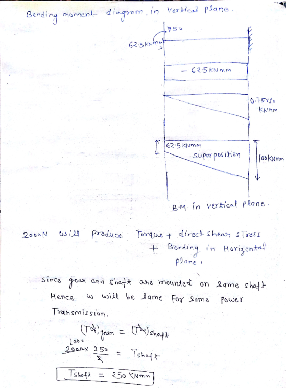
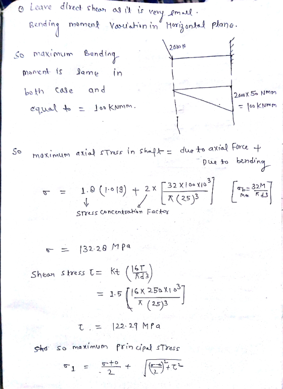
7. (15 pts) Consider a shaft that is rotating at 150 rpm driving a bevel gear...
 7. (15 pts) Consider a shaft that is rotating at 150 rpm driving a bevel gear as shown The shaft is below. supported by bearings at locations A and B. A is the thrust bearing. The motor input torque i by the torque at the gear. 0.4 FL F+ z direction) 0.2 Ft 35 mmm 50 mm Motor torque 15 mm50 mm dia a. (10 pts) Find the equivalent mean and alternating stresses at the location along the shaft axis...
In the figure below, a rotating shaft (for speed reducing gearbox) is subjected to radial forces at A= 400 lbr
 In the figure below, a rotating shaft (for speed reducing gearbox) is subjected to radial forces at A= 400 lbr .and at C = 800 Ibr. These radial forces are caused by spur gears mounted to shaft (a result of the pressure angle of the teeth, 20 degrees) that mesh with 2 other spur gears, not shown. Also, The shaft transmits a constant torque of 11110 in-lbr (925 ft-lbr) due to the tangential force (Wt: transmitted load) at C of...
A portion of a shaft where a gear is to be mounted has diameter of 50...
 A portion of a shaft where a gear is to be mounted has diameter of 50 mm. The gear transmits 335 N-m of torque. The shaft is to be made of SAE 1040 cold-drawn steel. The gear is made from SAE 8650 OQT 1000 steel The width of the hub of the gear mounted at this location is 45 mm. Design the key. The standard key dimension for a 50-mm-diameter shaft would be 14mm '9 mm Q-1 a rectangular. Material...
Problem 1 (a) (200 points) Shaft fatigue strength In the figure below, a rotating shaft (for...
 Problem 1 (a) (200 points) Shaft fatigue strength In the figure below, a rotating shaft (for speed reducing gearbox) is subjected to radial forces at A-400 lbrand at C-800 iht. These radial forces are caused by spur gears mounted to shar (a result of the pressure angle of the teeth, 20 degrees) that mesh with 2 other spur gears, not shown. Also, The shaft transmits a constant torque of 11110 in-Ibr (925 - due to the tangential force (s: transmitted...
The figure above shows two spur gears mounted on a shaft at A and C. This...
 The figure above shows two spur gears mounted on a shaft at A and C. This shaft gear assembly is supported on two pedestal bearings at D and Brespectively. These bearing supports act as simple supports. Neglect the weight of the shaft and the gears. The force on gear 1 is shown at an angle with respect to the vertical "y" axis and the force on gear 2 (Fc-1000 N) is shown at an angle with respect to the horizontal...
7-25 A shaft is to be designed to support the spur pinion and helical gear shown in the figure on two bearings spaced 700 mm center-to-center. Bearing A is a cylindrical roller and is to take onl...
 7-25 A shaft is to be designed to support the spur pinion and helical gear shown in the figure on two bearings spaced 700 mm center-to-center. Bearing A is a cylindrical roller and is to take only radial load; bearingB is to take the thrust load of 900 N produced by the helical gear and its share of the radial load. The bearing at B can be a bal bearing. The radial loads of both gears are in the same...
1) [40 pts] Determination of minimum shaft diameter using DE-Gerber, DE-ASME Elliptic, DE-Soderberg, and DE-Goodman criteria...
 1) [40 pts] Determination of minimum shaft diameter using DE-Gerber, DE-ASME Elliptic, DE-Soderberg, and DE-Goodman criteria A shaft is loaded in bending and torsion such that M. = 66 Nm, T. = 42.496 Nm, Mm = 51.858 Nm, and Tm = 33 N m. For the shaft, S, = 700 MPa and S, = 560 MPa, and a fully corrected endurance limit of S, = 210 MPa is assumed. Let K = 2.2 and Kis = 1.8. With a design...
 The rotating solid steel shaft is simply supported by bearings at points B and C and is driven by a gear (not shown) which meshes with the spur gear at D, which has a 150-mm pitch diameter. The force F from the drive gear acts at a pressure angle of 20°. The shaft transmits a torque to point A of T 400 N m. The shaft is machined from steel with S, 420 MPa and Su 560 MPa. Using a...
 Please answer A and B.
The rotating solid stedl shaft is simply supported by bearings at points B and C and is driven by a gear (not shown) which meshes with the spur gear at D, which has a 150-mm pitch diameter. The force F from the drive gear acts at a pressure angle of 20. The shaft transmits a torque to point A of TA-340 N m. The shaft is machined from steel with Sy- 420 MPa and Sut-560...
Please answer A and B.
The rotating solid stedl shaft is simply supported by bearings at points B and C and is driven by a gear (not shown) which meshes with the spur gear at D, which has a 150-mm pitch diameter. The force F from the drive gear acts at a pressure angle of 20. The shaft transmits a torque to point A of TA-340 N m. The shaft is machined from steel with Sy- 420 MPa and Sut-560...
 7. (15 pts) Consider a shaft that is rotating at 150 rpm driving a bevel gear as shown The shaft is below. supported by bearings at locations A and B. A is the thrust bearing. The motor input torque i by the torque at the gear. 0.4 FL F+ z direction) 0.2 Ft 35 mmm 50 mm Motor torque 15 mm50 mm dia a. (10 pts) Find the equivalent mean and alternating stresses at the location along the shaft axis...
 A portion of a shaft where a gear is to be mounted has diameter of 50 mm. The gear transmits 335 N-m of torque. The shaft is to be made of SAE 1040 cold-drawn steel. The gear is made from SAE 8650 OQT 1000 steel The width of the hub of the gear mounted at this location is 45 mm. Design the key. The standard key dimension for a 50-mm-diameter shaft would be 14mm '9 mm Q-1 a rectangular. Material...
 Problem 1 (a) (200 points) Shaft fatigue strength In the figure below, a rotating shaft (for speed reducing gearbox) is subjected to radial forces at A-400 lbrand at C-800 iht. These radial forces are caused by spur gears mounted to shar (a result of the pressure angle of the teeth, 20 degrees) that mesh with 2 other spur gears, not shown. Also, The shaft transmits a constant torque of 11110 in-Ibr (925 - due to the tangential force (s: transmitted...
 The figure above shows two spur gears mounted on a shaft at A and C. This shaft gear assembly is supported on two pedestal bearings at D and Brespectively. These bearing supports act as simple supports. Neglect the weight of the shaft and the gears. The force on gear 1 is shown at an angle with respect to the vertical "y" axis and the force on gear 2 (Fc-1000 N) is shown at an angle with respect to the horizontal...
 7-25 A shaft is to be designed to support the spur pinion and helical gear shown in the figure on two bearings spaced 700 mm center-to-center. Bearing A is a cylindrical roller and is to take only radial load; bearingB is to take the thrust load of 900 N produced by the helical gear and its share of the radial load. The bearing at B can be a bal bearing. The radial loads of both gears are in the same...
 1) [40 pts] Determination of minimum shaft diameter using DE-Gerber, DE-ASME Elliptic, DE-Soderberg, and DE-Goodman criteria A shaft is loaded in bending and torsion such that M. = 66 Nm, T. = 42.496 Nm, Mm = 51.858 Nm, and Tm = 33 N m. For the shaft, S, = 700 MPa and S, = 560 MPa, and a fully corrected endurance limit of S, = 210 MPa is assumed. Let K = 2.2 and Kis = 1.8. With a design...
Most questions answered within 3 hours.
-
3) What are the typical social structures in a global city?
asked 32 minutes ago -
Luther Corporation
Consolidated Balance Sheet
December 31, 2019 and 2018 (in $ millions)
Assets
2019
2018...
asked 34 minutes ago -
(Expected rate of return and risk) Carter Inc. is evaluating a
security. Calculate the investment’s expected...
asked 3 hours ago -
What specific indicators can point to lack of progress for
African Americans in American society?
asked 4 hours ago -
1-The Electrons in a beam are moving at 2.7×10⁸ m/s in an
electric field of 15000...
asked 4 hours ago -
A gas tank is a vertical cylinder. It has a radius of 1m, a
height of...
asked 4 hours ago -
Accent Software faces the following conditions. All of these
support Accent’s use of a market-penetration pricing...
asked 5 hours ago -
A mathematically inclined friend emails you the following
instructions: "Meet me in the cafeteria the first...
asked 5 hours ago -
A monopoly sells in two countries . The demand curves in the two
countries are p1...
asked 6 hours ago -
A .15kg rubber ball is bounced off a wall. Before hitting the
wall, the ball moves...
asked 7 hours ago -
A manufacturing company preparing to build a new plant is
considering three potential locations for it....
asked 7 hours ago -
B. If compound Y has approximately the same values of solubility
in toluene as compound X,...
asked 8 hours ago