
Homework Answers
Add Answer to:
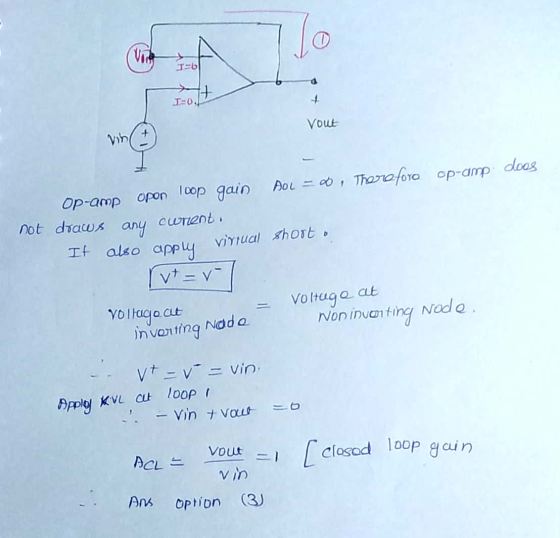
D Question 28 What is the voltage gain of the Op Amp Circuit in the picture...
D Question 23 What type of Op Amp Circuit is in the picture below? 16 Voltage...
 D Question 23 What type of Op Amp Circuit is in the picture below? 16 Voltage Follower Noninverting Amplifier Summing Amplifier Inverting Amplifier
The input to the below op-amp circuit is the source voltage vi(t) and the response is...
 The input to the below op-amp circuit is the source voltage vi(t) and the response is the voltage across Rư, vo(t). Design this circuit to satisfy the following two specifications: (a) The phase shift at w = 1000 rad/s is 225 degree. (b) The gain at high frequencies is 10. Ri C = 0.1 uF vilo o Rız volt)
Assume the op-amp below is used as a comparator circuit and that the op-amp is powered...
 Assume the op-amp below is used as a comparator circuit and that
the op-amp is powered by a bipolar
+/- 15 V power supply. If the reference voltage Vref = -9 V and the
input voltage is VI = 12 V,
determine the output voltage, VO, of the op-amp. Assume the
open-loop gain, A, is very large and
consider saturation effects. Include units in your answer.
VCC Vi V. + + Vref EE
Assume the op-amp below is used as a comparator circuit and that
the op-amp is powered by a bipolar
+/- 15 V power supply. If the reference voltage Vref = -9 V and the
input voltage is VI = 12 V,
determine the output voltage, VO, of the op-amp. Assume the
open-loop gain, A, is very large and
consider saturation effects. Include units in your answer.
VCC Vi V. + + Vref EE
Assuming an ideal op-amp, find the voltage gain G Two Question Plz!!!!!!!!!!!!!!!!!!!! 1. Assuming an ideal...
 Assuming an ideal op-amp, find the voltage gain G
Two Question Plz!!!!!!!!!!!!!!!!!!!!
1. Assuming an ideal op-amp, find the voltage gain G 0 0 Answer: G 1.03 2. Assuming an ideal op-amp, find the voltage gain G 18 kΩ 100 Ω 150 Ω 0 Answer: G-24
Assuming an ideal op-amp, find the voltage gain G
Two Question Plz!!!!!!!!!!!!!!!!!!!!
1. Assuming an ideal op-amp, find the voltage gain G 0 0 Answer: G 1.03 2. Assuming an ideal op-amp, find the voltage gain G 18 kΩ 100 Ω 150 Ω 0 Answer: G-24
Good morning, I need help with the following, they all relate to OP Amps. Thanks in advance. 2 value 10.00 points Problem 05.010 An op amp voltage divider Find the voltage gain vo/vs of the circ...
 Good morning, I need help with the following, they all relate to
OP Amps. Thanks in advance.
2 value 10.00 points Problem 05.010 An op amp voltage divider Find the voltage gain vo/vs of the circuit given below, where R1-18 kΩ and R2-14 k 2. 20 kΩ R1 1% R2 The voltage gain vo/vs of the circuit is Hints Referene eBook & Resources Hint#1 Check my work 3. 1000 points value Problem 05.025-Voltage follower Calculate the output voltage vo in...
Good morning, I need help with the following, they all relate to
OP Amps. Thanks in advance.
2 value 10.00 points Problem 05.010 An op amp voltage divider Find the voltage gain vo/vs of the circuit given below, where R1-18 kΩ and R2-14 k 2. 20 kΩ R1 1% R2 The voltage gain vo/vs of the circuit is Hints Referene eBook & Resources Hint#1 Check my work 3. 1000 points value Problem 05.025-Voltage follower Calculate the output voltage vo in...
A. (10 pts) Implement the voltage amplifier shown below using an ideal op amp circuit. You have o...
 a. (10 pts) Implement the voltage amplifier shown below using an ideal op amp circuit. You have one op amp available for this circuit, and a range of resistors with values from 1 kΩ to 100 ka. Draw the schematic of your op amp circuit, labeling resistor values. Make sure the gain, input resistance, and output resistance of your circuit matches the model in the schematic. R=012 *100v, RL 100 b. (5 pts) Your amplifier circuit should have a frequency...
For the circuit in Figure below, if the op amp is ideal and if the voltage...
 For the circuit in Figure below, if the op amp is ideal and if the voltage vs-O current io is? 10 V (+ Us Select one: a. 10 mA O b. (10/12) mA C. -2.5 mA
Figure 2 shows a multiple op-amp networks combined to produce a gain amplifier circuit. For the...
 Figure 2 shows a multiple op-amp networks combined to produce a gain amplifier circuit. For the given circuit: (i) Name all the type of op-amp circuits shown by Op-Amp 1 until Op-Amp 5. (ii) Calculate the output of each Op-Amp 1 until Op-Amp 4. Assume Vin = 10mV (iii) Determine the output voltage at the last Op-Amp 5. From this value, calculate the gain produced by this Op-Amp network in overall, by using Av=Vos / Vin equation. [10 Marks] CO3,...
is the range of gain values expected from such a circuit? An inverting op amp circuit...
 is the range of gain values
expected from such a circuit?
An inverting op amp circuit is fabricated with the resistors R, and R2 having x% tolerance (that is, the value of each resistance can deviate from the nominal value by as much as x%). What is the tolerance on the realized closed-loop gain? As- sume the op amp to be ideal. If the nominal closed-loop gain is -100 V/V and x = 5, what
is the range of gain values
expected from such a circuit?
An inverting op amp circuit is fabricated with the resistors R, and R2 having x% tolerance (that is, the value of each resistance can deviate from the nominal value by as much as x%). What is the tolerance on the realized closed-loop gain? As- sume the op amp to be ideal. If the nominal closed-loop gain is -100 V/V and x = 5, what
5. A differential op-amp circuit needs to be designed to implement linear voltage measuring function =2.261,...
 5. A differential op-amp circuit needs to be designed to implement linear voltage measuring function =2.261, where input voltage is the differential output voltage measurement V.-.-V, of a Wheatstone bridge circuit in stage-1 signal conditioning (1) Provide values of resistors that define the circuit's gain as A (2) Proved the required values of input voltages and V. of the designed differential op amp circuit (3) Provide the schematics of the designed stage-2 differential op-amp circuit and its connection to the...
 D Question 23 What type of Op Amp Circuit is in the picture below? 16 Voltage Follower Noninverting Amplifier Summing Amplifier Inverting Amplifier
 The input to the below op-amp circuit is the source voltage vi(t) and the response is the voltage across Rư, vo(t). Design this circuit to satisfy the following two specifications: (a) The phase shift at w = 1000 rad/s is 225 degree. (b) The gain at high frequencies is 10. Ri C = 0.1 uF vilo o Rız volt)
 Assume the op-amp below is used as a comparator circuit and that
the op-amp is powered by a bipolar
+/- 15 V power supply. If the reference voltage Vref = -9 V and the
input voltage is VI = 12 V,
determine the output voltage, VO, of the op-amp. Assume the
open-loop gain, A, is very large and
consider saturation effects. Include units in your answer.
VCC Vi V. + + Vref EE
Assume the op-amp below is used as a comparator circuit and that
the op-amp is powered by a bipolar
+/- 15 V power supply. If the reference voltage Vref = -9 V and the
input voltage is VI = 12 V,
determine the output voltage, VO, of the op-amp. Assume the
open-loop gain, A, is very large and
consider saturation effects. Include units in your answer.
VCC Vi V. + + Vref EE
 Assuming an ideal op-amp, find the voltage gain G
Two Question Plz!!!!!!!!!!!!!!!!!!!!
1. Assuming an ideal op-amp, find the voltage gain G 0 0 Answer: G 1.03 2. Assuming an ideal op-amp, find the voltage gain G 18 kΩ 100 Ω 150 Ω 0 Answer: G-24
Assuming an ideal op-amp, find the voltage gain G
Two Question Plz!!!!!!!!!!!!!!!!!!!!
1. Assuming an ideal op-amp, find the voltage gain G 0 0 Answer: G 1.03 2. Assuming an ideal op-amp, find the voltage gain G 18 kΩ 100 Ω 150 Ω 0 Answer: G-24
 Good morning, I need help with the following, they all relate to
OP Amps. Thanks in advance.
2 value 10.00 points Problem 05.010 An op amp voltage divider Find the voltage gain vo/vs of the circuit given below, where R1-18 kΩ and R2-14 k 2. 20 kΩ R1 1% R2 The voltage gain vo/vs of the circuit is Hints Referene eBook & Resources Hint#1 Check my work 3. 1000 points value Problem 05.025-Voltage follower Calculate the output voltage vo in...
Good morning, I need help with the following, they all relate to
OP Amps. Thanks in advance.
2 value 10.00 points Problem 05.010 An op amp voltage divider Find the voltage gain vo/vs of the circuit given below, where R1-18 kΩ and R2-14 k 2. 20 kΩ R1 1% R2 The voltage gain vo/vs of the circuit is Hints Referene eBook & Resources Hint#1 Check my work 3. 1000 points value Problem 05.025-Voltage follower Calculate the output voltage vo in...
 a. (10 pts) Implement the voltage amplifier shown below using an ideal op amp circuit. You have one op amp available for this circuit, and a range of resistors with values from 1 kΩ to 100 ka. Draw the schematic of your op amp circuit, labeling resistor values. Make sure the gain, input resistance, and output resistance of your circuit matches the model in the schematic. R=012 *100v, RL 100 b. (5 pts) Your amplifier circuit should have a frequency...
 For the circuit in Figure below, if the op amp is ideal and if the voltage vs-O current io is? 10 V (+ Us Select one: a. 10 mA O b. (10/12) mA C. -2.5 mA
 Figure 2 shows a multiple op-amp networks combined to produce a gain amplifier circuit. For the given circuit: (i) Name all the type of op-amp circuits shown by Op-Amp 1 until Op-Amp 5. (ii) Calculate the output of each Op-Amp 1 until Op-Amp 4. Assume Vin = 10mV (iii) Determine the output voltage at the last Op-Amp 5. From this value, calculate the gain produced by this Op-Amp network in overall, by using Av=Vos / Vin equation. [10 Marks] CO3,...
 is the range of gain values
expected from such a circuit?
An inverting op amp circuit is fabricated with the resistors R, and R2 having x% tolerance (that is, the value of each resistance can deviate from the nominal value by as much as x%). What is the tolerance on the realized closed-loop gain? As- sume the op amp to be ideal. If the nominal closed-loop gain is -100 V/V and x = 5, what
is the range of gain values
expected from such a circuit?
An inverting op amp circuit is fabricated with the resistors R, and R2 having x% tolerance (that is, the value of each resistance can deviate from the nominal value by as much as x%). What is the tolerance on the realized closed-loop gain? As- sume the op amp to be ideal. If the nominal closed-loop gain is -100 V/V and x = 5, what
 5. A differential op-amp circuit needs to be designed to implement linear voltage measuring function =2.261, where input voltage is the differential output voltage measurement V.-.-V, of a Wheatstone bridge circuit in stage-1 signal conditioning (1) Provide values of resistors that define the circuit's gain as A (2) Proved the required values of input voltages and V. of the designed differential op amp circuit (3) Provide the schematics of the designed stage-2 differential op-amp circuit and its connection to the...
Most questions answered within 3 hours.
-
Derive the long wavelength limit of the Planck energy density
distribution
asked 1 minute ago -
Phosphorous + bromine = phosphorous tribromide. If 35.0 g of
bromine are reacted and 27.9 grams...
asked 11 minutes ago -
Calculate the pH of each of the following solutions.
0.50 M HBr
3.1×10⁻⁴ M KOH
4.2×10⁻⁵...
asked 3 hours ago -
For the year ended December 31, Depot Max’s cost of merchandise
sold was $85,600. Inventory at the...
asked 3 hours ago -
Week 10 - Professional Memo Assignment
Professional Memo Assignment
Your mission for this week, should you...
asked 3 hours ago -
Write a Python program that stores the data for each
player on the team, and it...
asked 3 hours ago -
In
the last 3 months, mike never knows when he is going to get his
allowance...
asked 4 hours ago -
Is Ca(OH)2 a Bronsted base, Lewis base, or both? Why?
asked 4 hours ago -
1A- Why don’t voters complain about U.S. tariffs on imported
sugar?
Because sugar is only a...
asked 4 hours ago -
Cash Payback Period
Primera Banco is evaluating two capital investment proposals for
a drive-up ATM kiosk,...
asked 4 hours ago -
Create a button in Swift (Xcode) that will create a charge,
create a charge using Stripe's...
asked 4 hours ago -
The reaction rate of CO and NO2 in the reaction
CO(g) + NO2(g) → CO2(g) +...
asked 4 hours ago