
Homework Answers


Add Answer to:
Q1. For the cantilever beam and loading shown with circular section of 60 mm diameter and...
For the cantilever beam and loading shown, determine the slope and deflection at point B. Use...
 For the cantilever beam and loading shown, determine the slope and deflection at point B. Use P 5 kN and E 200 GPa. (Round the final answers to two decimal places.) S100 X 11.5 0.75 m 0.5 m The slope at point B is The deflection at point B is x 10-3 rad. mm ↓
For the cantilever beam and loading shown, use the method of superposition to determine (a) the...
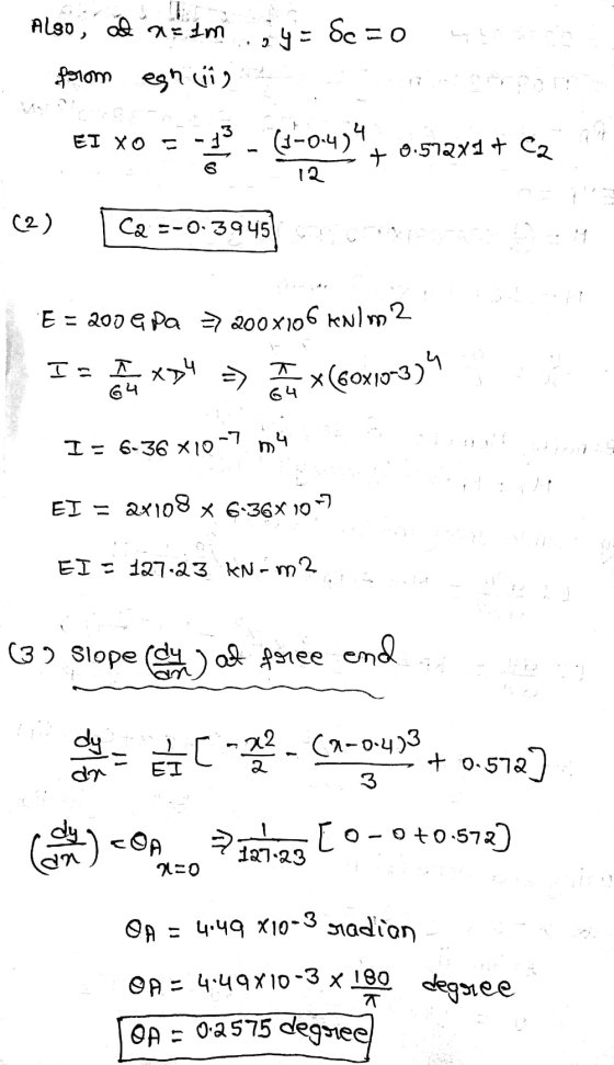
 For the cantilever beam and loading shown, use the method of superposition to determine (a) the slope at point A, (b) the deflection at point A. Use E 200 GPa. Hint: Use the expression found in Problem 1 for the tri angular load. 120 kN/m W360 × 64 20 kN 2.1 m
Check my work For the cantilever beam and loading shown, determine the slope and deflection at...
 Check my work For the cantilever beam and loading shown, determine the slope and deflection at end C. Use P = 9 kN and E= 200 GPa. (Round the final answers to two decimal places.) P Р B I A $100 X 11.5 -0.75 m 0.5 m The slope at end Cis The deflection at end Cis x 10m rad . -3 mm.
Question 4 (25 marks) For the beam and loading shown in Figure 4, knowing that a...
 Question 4 (25 marks) For the beam and loading shown in Figure 4, knowing that a GPa, determine (a) the slope at support A, (b) the deflection at point C. (using integration method) 2m, w 50KN/m and E 200 80 w 20 60 Unit: mm A 10 60 В а 20 6 m 80 (a) Beam loading (b) Cross section Figure 4
For the cantilever steel beam [E 190 GPa; deflection VA at A 110 x 106 mm*],...
 For the cantilever steel beam [E 190 GPa; deflection VA at A 110 x 106 mm*], use the double-integration method to determine the Assume L = 1.6 m, P = 59 kN, and wo = 106 kN/m. Answer: VA = the tolerance is +/-296
The cross section of the cantilever beam loaded as shown in Fig. 8-20 is rectangular, 50 × 75 mm. The bar, 1 m long, i...
 The cross section of the cantilever beam loaded as shown in
Fig. 8-20 is rectangular, 50 × 75 mm. The bar, 1 m long, is
aluminum for which E = 65 GPa. Determine the permissible maximum
intensity of loading if the maximum deflection is not to exceed 5
mm and the maximum stress is not to exceed 50 MPa.
Ans. w0 = 14.1 kN/m and 17.1 kN/m. Select 14.1 kN/m.
oment 3 Fig. 8-20
oment 3 Fig. 8-20
The cross section of the cantilever beam loaded as shown in
Fig. 8-20 is rectangular, 50 × 75 mm. The bar, 1 m long, is
aluminum for which E = 65 GPa. Determine the permissible maximum
intensity of loading if the maximum deflection is not to exceed 5
mm and the maximum stress is not to exceed 50 MPa.
Ans. w0 = 14.1 kN/m and 17.1 kN/m. Select 14.1 kN/m.
oment 3 Fig. 8-20
oment 3 Fig. 8-20
2. For the cantilever beam and loading 165 GPa. Shown, calculate the maximum deflection of the...
 2. For the cantilever beam and loading 165 GPa. Shown, calculate the maximum deflection of the beam. Use E- cal 26 kN/m W250 x 28.4 s kN 2.2 m 0.5 m
8. The cantilever beam in Figure Q8 subjects to concentrated loading. The cross section geometry gives...
 8. The cantilever beam in Figure Q8 subjects to concentrated loading. The cross section geometry gives the second moment of area / 100 x 10 m. The longitudinal geometry of the beam: a 2 m, b 1 m. The material of the beam: Young's modulus E 200 GPa. The loading: concentrated force P 10 KN. (a) Determine the reactions to the beam at the fixed end. (b) Determine the rotation angle at point x-a (c) (Determine the deflection at the...
Consider the beam and loading shown. Given: P 8.8 kN 03 m 40 mm 12 mm...
 Consider the beam and loading shown. Given: P 8.8 kN 03 m 40 mm 12 mm 150 mm 12 mm 100 mm -200 mm 1.5 m 1. Determine the largest shearing stress in section n-n. (Round the final answer to the nearest whole number.) kPa. The largest shearing stress is 02019 McGraw HIll Bducation Al rights cosorved For the beam and loading shown, consider section-nand take P 177 kN. 160 mm 20 mm 100 mm 30 mm 500 mm- 500...
A cantilever beam of a channel section is loaded at its half-length, as shown in Figure Q2. The Young's modulus of the material is 200 GPa. Determine the deflection at the free end. [12.5 marks]...
 A cantilever beam of a channel section is loaded at its half-length, as shown in Figure Q2. The Young's modulus of the material is 200 GPa. Determine the deflection at the free end. [12.5 marks] 25 mm 25 mm 5 kN a -a 少a 6 mm 200 mm Figure Q2
A cantilever beam of a channel section is loaded at its half-length, as shown in Figure Q2. The Young's modulus of the material is 200 GPa. Determine the deflection at...
A cantilever beam of a channel section is loaded at its half-length, as shown in Figure Q2. The Young's modulus of the material is 200 GPa. Determine the deflection at the free end. [12.5 marks] 25 mm 25 mm 5 kN a -a 少a 6 mm 200 mm Figure Q2
A cantilever beam of a channel section is loaded at its half-length, as shown in Figure Q2. The Young's modulus of the material is 200 GPa. Determine the deflection at...
 For the cantilever beam and loading shown, determine the slope and deflection at point B. Use P 5 kN and E 200 GPa. (Round the final answers to two decimal places.) S100 X 11.5 0.75 m 0.5 m The slope at point B is The deflection at point B is x 10-3 rad. mm ↓
 For the cantilever beam and loading shown, use the method of superposition to determine (a) the slope at point A, (b) the deflection at point A. Use E 200 GPa. Hint: Use the expression found in Problem 1 for the tri angular load. 120 kN/m W360 × 64 20 kN 2.1 m
 Check my work For the cantilever beam and loading shown, determine the slope and deflection at end C. Use P = 9 kN and E= 200 GPa. (Round the final answers to two decimal places.) P Р B I A $100 X 11.5 -0.75 m 0.5 m The slope at end Cis The deflection at end Cis x 10m rad . -3 mm.
 Question 4 (25 marks) For the beam and loading shown in Figure 4, knowing that a GPa, determine (a) the slope at support A, (b) the deflection at point C. (using integration method) 2m, w 50KN/m and E 200 80 w 20 60 Unit: mm A 10 60 В а 20 6 m 80 (a) Beam loading (b) Cross section Figure 4
 For the cantilever steel beam [E 190 GPa; deflection VA at A 110 x 106 mm*], use the double-integration method to determine the Assume L = 1.6 m, P = 59 kN, and wo = 106 kN/m. Answer: VA = the tolerance is +/-296
 The cross section of the cantilever beam loaded as shown in
Fig. 8-20 is rectangular, 50 × 75 mm. The bar, 1 m long, is
aluminum for which E = 65 GPa. Determine the permissible maximum
intensity of loading if the maximum deflection is not to exceed 5
mm and the maximum stress is not to exceed 50 MPa.
Ans. w0 = 14.1 kN/m and 17.1 kN/m. Select 14.1 kN/m.
oment 3 Fig. 8-20
oment 3 Fig. 8-20
The cross section of the cantilever beam loaded as shown in
Fig. 8-20 is rectangular, 50 × 75 mm. The bar, 1 m long, is
aluminum for which E = 65 GPa. Determine the permissible maximum
intensity of loading if the maximum deflection is not to exceed 5
mm and the maximum stress is not to exceed 50 MPa.
Ans. w0 = 14.1 kN/m and 17.1 kN/m. Select 14.1 kN/m.
oment 3 Fig. 8-20
oment 3 Fig. 8-20
 2. For the cantilever beam and loading 165 GPa. Shown, calculate the maximum deflection of the beam. Use E- cal 26 kN/m W250 x 28.4 s kN 2.2 m 0.5 m
 8. The cantilever beam in Figure Q8 subjects to concentrated loading. The cross section geometry gives the second moment of area / 100 x 10 m. The longitudinal geometry of the beam: a 2 m, b 1 m. The material of the beam: Young's modulus E 200 GPa. The loading: concentrated force P 10 KN. (a) Determine the reactions to the beam at the fixed end. (b) Determine the rotation angle at point x-a (c) (Determine the deflection at the...
 Consider the beam and loading shown. Given: P 8.8 kN 03 m 40 mm 12 mm 150 mm 12 mm 100 mm -200 mm 1.5 m 1. Determine the largest shearing stress in section n-n. (Round the final answer to the nearest whole number.) kPa. The largest shearing stress is 02019 McGraw HIll Bducation Al rights cosorved For the beam and loading shown, consider section-nand take P 177 kN. 160 mm 20 mm 100 mm 30 mm 500 mm- 500...
 A cantilever beam of a channel section is loaded at its half-length, as shown in Figure Q2. The Young's modulus of the material is 200 GPa. Determine the deflection at the free end. [12.5 marks] 25 mm 25 mm 5 kN a -a 少a 6 mm 200 mm Figure Q2
A cantilever beam of a channel section is loaded at its half-length, as shown in Figure Q2. The Young's modulus of the material is 200 GPa. Determine the deflection at...
A cantilever beam of a channel section is loaded at its half-length, as shown in Figure Q2. The Young's modulus of the material is 200 GPa. Determine the deflection at the free end. [12.5 marks] 25 mm 25 mm 5 kN a -a 少a 6 mm 200 mm Figure Q2
A cantilever beam of a channel section is loaded at its half-length, as shown in Figure Q2. The Young's modulus of the material is 200 GPa. Determine the deflection at...
Most questions answered within 3 hours.
-
1. why is toluene a stronger nucleophile than benzene?
2.why is phenol a stronger nucleophile than...
asked 12 minutes ago -
4. How can you solve for the density of the liquid from the
slope? Please show...
asked 12 minutes ago -
when 2053 j of heat is added to 46.3 g of hexane C6H14 the
temperature increases...
asked 36 minutes ago -
I need new and unique answers, please. (Use your own words,
don't copy and paste), Please...
asked 39 minutes ago -
MCL 445.111 et seq. deals with Home Solicitation Sales.
MCL stands for Michigan Compiled Laws which...
asked 29 minutes ago -
Which of the following items may not create an NOL?
a.
sole proprietorship loss
b.
personal...
asked 34 minutes ago -
A hypothetical solution forms between a solid and a liquid. The
values of the thermodynamic quantities...
asked 33 minutes ago -
a)An ideal heat pump is being considered for use in heating an
environment with a temperature...
asked 36 minutes ago -
.
Convert the following pairs of voltage and current waveforms to
phasor form. Each pair of...
asked 37 minutes ago -
A 6.5 cm diameter ball has a terminal speed of 22 m/s. What is
the ball's...
asked 51 minutes ago -
Name two areas of the human body with the highest concentration
of lymph nodes and speculate...
asked 55 minutes ago -
Angel Corporation has $10,000,000 of
8.0% 25 year bonds dated May 1, 2018 with interest payable...
asked 1 hour ago