
Homework Answers

Add Answer to:
R S2 Sy R: с 6. A capacitor, three batteries, three resistors, and three switches (S1,...
A circuit is wired up as shown below. The capacitor is initially uncharged and switches S1 and S2 are initially open.
 A circuit is wired up as shown below. The capacitor is initially uncharged and switches S1 and S2 are initially open.1) What is the voltage across the capacitor immediately after
switch S1 is closed?Vc = 0Vc = VVc = 2V/32) What is the voltage across the capacitor after switch S1 has
been closed for a very long time?Vc = 0Vc = VVc = 2V/33) After being closed a long time, switch 1 is opened and switch
2 is closed. What...
A circuit is wired up as shown below. The capacitor is initially uncharged and switches S1 and S2 are initially open.1) What is the voltage across the capacitor immediately after
switch S1 is closed?Vc = 0Vc = VVc = 2V/32) What is the voltage across the capacitor after switch S1 has
been closed for a very long time?Vc = 0Vc = VVc = 2V/33) After being closed a long time, switch 1 is opened and switch
2 is closed. What...
The figure shows a circuit cantaining three switches, labeled S1, S2, and S3. Find the current...
 The figure shows a circuit cantaining three
switches, labeled S1, S2, and S3. Find the current at "a" for all
possible combinations of switch settings. Put ? = 70
V, R1 = 25 ?, and R2 = 9 ?.
Assume that the battery has no resistance.
Current at "a" for S2 and S3 closed and S1
open?
Current at "a" for S2 closed and S1 and S3
open?
The figure shows a circuit cantaining three
switches, labeled S1, S2, and S3. Find the current at "a" for all
possible combinations of switch settings. Put ? = 70
V, R1 = 25 ?, and R2 = 9 ?.
Assume that the battery has no resistance.
Current at "a" for S2 and S3 closed and S1
open?
Current at "a" for S2 closed and S1 and S3
open?
The figure shows a circuit containing three switches, labeled S1, S2, and S3. Find the current...
 The figure shows a circuit containing three switches, labeled
S1, S2, and S3. Find the current at "a" for all possible
combinations of switch settings. Put e = 90 V, R1 = 20 Ohm, and R2
= 10 Ohm. Assume that the battery has no resistance.
a. Current at "a" for S1 and S3 closed, S2 open (in A)
b. Current at "a" for S1 and S2 closed and S3 open (in A)
c. Current at "a" for SI and...
The figure shows a circuit containing three switches, labeled
S1, S2, and S3. Find the current at "a" for all possible
combinations of switch settings. Put e = 90 V, R1 = 20 Ohm, and R2
= 10 Ohm. Assume that the battery has no resistance.
a. Current at "a" for S1 and S3 closed, S2 open (in A)
b. Current at "a" for S1 and S2 closed and S3 open (in A)
c. Current at "a" for SI and...
The circuit of the figure shows a capacitor, two ideal batteries, two resistors, and a switch...
 The
circuit of the figure shows a capacitor, two ideal batteries, two
resistors, and a switch S. Initially S has been open for a long
time. If it is then closed for a long time, what is the change in
the charge on the capacitor? Assume C = 43 μF, 1 = 1.7 V, 2 = 6.0
V, R1 = 0.41 Ω, and R2 = 0.59 Ω.
The
circuit of the figure shows a capacitor, two ideal batteries, two
resistors, and a switch S. Initially S has been open for a long
time. If it is then closed for a long time, what is the change in
the charge on the capacitor? Assume C = 43 μF, 1 = 1.7 V, 2 = 6.0
V, R1 = 0.41 Ω, and R2 = 0.59 Ω.
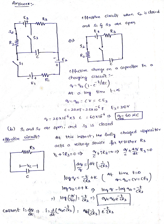
5. The circuit below has two capacitors, three resistors, a battery and two switches. The switches,...
 5. The circuit below has two capacitors, three resistors, a battery and two switches. The switches, S1 and S2, have been open for a long time and the capacitors are uncharged. At time t O both switches arc closed. 1MuF = 10^-6 F. a. Immediately after both switches are closed, what is the current I2? b. After the switches have been closed for a very long time, what is the current I1? c. After the switches have been closed for...
The figure below shows three resistors (Ri-15.5 ฉ circuit. R,. '80 , and R,. ii 50)...
 The figure below shows three resistors (Ri-15.5 ฉ circuit. R,. '80 , and R,. ii 50) and two batteries connected in a 40.0 V Ri 22.0 V AR (a) What is the current in each of the resistors? I3 (b) How much power is delivered to each of the resistors? P1
2) Shown below is a c R2 = 7 Ω, R3 = 24 Ω, R4 = 10 ircuit with two switches. Si and S2M = 15 V, V...
 2) Shown below is a c R2 = 7 Ω, R3 = 24 Ω, R4 = 10 ircuit with two switches. Si and S2M = 15 V, V.-5 V, V,-20 V, Rı = 15 Ω . 25s2 C,200F v -,,I -R, Г 2:0 start atp sition A. This creates two dependent circuits. The left circuit with only resistors '5 V-15A)(T)-YAG).2ov-ocharges the capacitor C, through resistor Rs with battery Vs(the capacitor is initially The switch 1 will start in the on/closed...
Question 7 Not complete The circuit below contains three resistors and a capacitor. The emf of...
 Question 7 Not complete The circuit below contains three resistors and a capacitor. The emf of the ideal battery is e. The direction of the current in each resistor and the capacitor is indicated by the arrows in the diagram. As indicated by the current, the capacitor is not fully charged at this moment. Points out of 14.00 www P Flag question Complete the values in the table. Complete the values in the table. Element AV (V) (A) Direction of...
Two batteries, a capacitor, and two light bulbs are connected by wires. The batteries have a...
 Two batteries, a capacitor, and two light bulbs are connected by
wires. The batteries have a potential difference emf, the capacitor
has capacitance C, and the bulbs have resistance R. Initially the
capacitor is uncharged and the switch has been closed.
A)Write down the three loop rules and the node rule for this
circuit and label the currents on the picture.
B) Find the initial currents running through each bulb.
C)What is the current running through each bulb a long...
Two batteries, a capacitor, and two light bulbs are connected by
wires. The batteries have a potential difference emf, the capacitor
has capacitance C, and the bulbs have resistance R. Initially the
capacitor is uncharged and the switch has been closed.
A)Write down the three loop rules and the node rule for this
circuit and label the currents on the picture.
B) Find the initial currents running through each bulb.
C)What is the current running through each bulb a long...
The circuit shown in the figure below contains three resistors (R1, R2, and R3) and three...
 The circuit shown in the figure below contains three resistors (R1, R2, and R3) and three batteries (VA, Vg, and Vc). The resistor values are: R7-2 Ohms, R-R3-4 Ohms, and the battery voltages are VA=25 V. V8-15 V, and Vc=20 V. When the circuit is connected, what will be the power dissipated by Rg? Vc R, VA VE R₂ R3 1.25 W 0 2.0 W 5.0 W O 6.25 W O 8.13 W The circuit shown in the figure contains...
 A circuit is wired up as shown below. The capacitor is initially uncharged and switches S1 and S2 are initially open.1) What is the voltage across the capacitor immediately after
switch S1 is closed?Vc = 0Vc = VVc = 2V/32) What is the voltage across the capacitor after switch S1 has
been closed for a very long time?Vc = 0Vc = VVc = 2V/33) After being closed a long time, switch 1 is opened and switch
2 is closed. What...
A circuit is wired up as shown below. The capacitor is initially uncharged and switches S1 and S2 are initially open.1) What is the voltage across the capacitor immediately after
switch S1 is closed?Vc = 0Vc = VVc = 2V/32) What is the voltage across the capacitor after switch S1 has
been closed for a very long time?Vc = 0Vc = VVc = 2V/33) After being closed a long time, switch 1 is opened and switch
2 is closed. What...
 The figure shows a circuit cantaining three
switches, labeled S1, S2, and S3. Find the current at "a" for all
possible combinations of switch settings. Put ? = 70
V, R1 = 25 ?, and R2 = 9 ?.
Assume that the battery has no resistance.
Current at "a" for S2 and S3 closed and S1
open?
Current at "a" for S2 closed and S1 and S3
open?
The figure shows a circuit cantaining three
switches, labeled S1, S2, and S3. Find the current at "a" for all
possible combinations of switch settings. Put ? = 70
V, R1 = 25 ?, and R2 = 9 ?.
Assume that the battery has no resistance.
Current at "a" for S2 and S3 closed and S1
open?
Current at "a" for S2 closed and S1 and S3
open?
 The figure shows a circuit containing three switches, labeled
S1, S2, and S3. Find the current at "a" for all possible
combinations of switch settings. Put e = 90 V, R1 = 20 Ohm, and R2
= 10 Ohm. Assume that the battery has no resistance.
a. Current at "a" for S1 and S3 closed, S2 open (in A)
b. Current at "a" for S1 and S2 closed and S3 open (in A)
c. Current at "a" for SI and...
The figure shows a circuit containing three switches, labeled
S1, S2, and S3. Find the current at "a" for all possible
combinations of switch settings. Put e = 90 V, R1 = 20 Ohm, and R2
= 10 Ohm. Assume that the battery has no resistance.
a. Current at "a" for S1 and S3 closed, S2 open (in A)
b. Current at "a" for S1 and S2 closed and S3 open (in A)
c. Current at "a" for SI and...
 The
circuit of the figure shows a capacitor, two ideal batteries, two
resistors, and a switch S. Initially S has been open for a long
time. If it is then closed for a long time, what is the change in
the charge on the capacitor? Assume C = 43 μF, 1 = 1.7 V, 2 = 6.0
V, R1 = 0.41 Ω, and R2 = 0.59 Ω.
The
circuit of the figure shows a capacitor, two ideal batteries, two
resistors, and a switch S. Initially S has been open for a long
time. If it is then closed for a long time, what is the change in
the charge on the capacitor? Assume C = 43 μF, 1 = 1.7 V, 2 = 6.0
V, R1 = 0.41 Ω, and R2 = 0.59 Ω.
 5. The circuit below has two capacitors, three resistors, a battery and two switches. The switches, S1 and S2, have been open for a long time and the capacitors are uncharged. At time t O both switches arc closed. 1MuF = 10^-6 F. a. Immediately after both switches are closed, what is the current I2? b. After the switches have been closed for a very long time, what is the current I1? c. After the switches have been closed for...
 The figure below shows three resistors (Ri-15.5 ฉ circuit. R,. '80 , and R,. ii 50) and two batteries connected in a 40.0 V Ri 22.0 V AR (a) What is the current in each of the resistors? I3 (b) How much power is delivered to each of the resistors? P1
 2) Shown below is a c R2 = 7 Ω, R3 = 24 Ω, R4 = 10 ircuit with two switches. Si and S2M = 15 V, V.-5 V, V,-20 V, Rı = 15 Ω . 25s2 C,200F v -,,I -R, Г 2:0 start atp sition A. This creates two dependent circuits. The left circuit with only resistors '5 V-15A)(T)-YAG).2ov-ocharges the capacitor C, through resistor Rs with battery Vs(the capacitor is initially The switch 1 will start in the on/closed...
 Question 7 Not complete The circuit below contains three resistors and a capacitor. The emf of the ideal battery is e. The direction of the current in each resistor and the capacitor is indicated by the arrows in the diagram. As indicated by the current, the capacitor is not fully charged at this moment. Points out of 14.00 www P Flag question Complete the values in the table. Complete the values in the table. Element AV (V) (A) Direction of...
 Two batteries, a capacitor, and two light bulbs are connected by
wires. The batteries have a potential difference emf, the capacitor
has capacitance C, and the bulbs have resistance R. Initially the
capacitor is uncharged and the switch has been closed.
A)Write down the three loop rules and the node rule for this
circuit and label the currents on the picture.
B) Find the initial currents running through each bulb.
C)What is the current running through each bulb a long...
Two batteries, a capacitor, and two light bulbs are connected by
wires. The batteries have a potential difference emf, the capacitor
has capacitance C, and the bulbs have resistance R. Initially the
capacitor is uncharged and the switch has been closed.
A)Write down the three loop rules and the node rule for this
circuit and label the currents on the picture.
B) Find the initial currents running through each bulb.
C)What is the current running through each bulb a long...
 The circuit shown in the figure below contains three resistors (R1, R2, and R3) and three batteries (VA, Vg, and Vc). The resistor values are: R7-2 Ohms, R-R3-4 Ohms, and the battery voltages are VA=25 V. V8-15 V, and Vc=20 V. When the circuit is connected, what will be the power dissipated by Rg? Vc R, VA VE R₂ R3 1.25 W 0 2.0 W 5.0 W O 6.25 W O 8.13 W The circuit shown in the figure contains...
Most questions answered within 3 hours.
-
Problem 16-51 Sales
Activity Variance (LO 16-3)Odessa, Inc., reports the following
information concerning operations for the...
asked 16 minutes ago -
Pictured on the right are thee point charges Q1 = 18.4 μC, Q2 =
-30.6 μC,...
asked 19 minutes ago -
A graduate student is conducting research in psychology and
needs to obtain the IQ scores of...
asked 55 minutes ago -
R2.84: There are 2 defective products in a production lot of 10.
An inspector randomly selected...
asked 2 hours ago -
Consider the following equilibrium system: COCl2(g) CO(g) +
Cl2(g) A 10.00 L evacuated flask is filled...
asked 2 hours ago -
1) What are the two distinct steps that one needs to perform
when developing a data...
asked 2 hours ago -
2) Write a C++ program that uses a class called “Degree” to
obtain the trigonometric
values...
asked 3 hours ago -
1. In eukaryotic cells the genomes of
&
asked 3 hours ago -
The standard enthalpy of propanol (C3H7OH) is -303.0 kJ/mol.
Compute both of the
gross and net...
asked 3 hours ago -
Why PWM using H-bridge for control motor speed is more power
effiecient than the linear amplifier...
asked 4 hours ago -
In 1999, Carly Fiorina famously said,"I hope that we are at a
point that everyone is...
asked 4 hours ago -
Individuals in a species of moth vary in wing color from white to
black, but all...
asked 4 hours ago