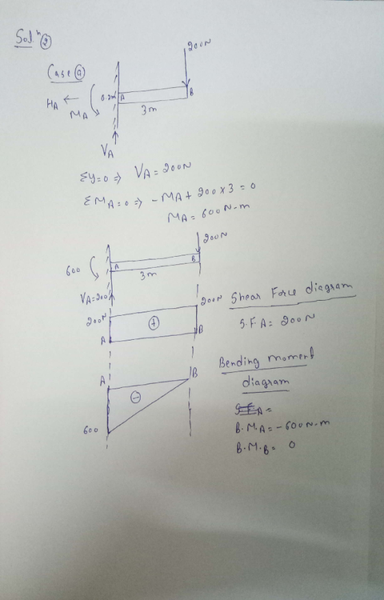
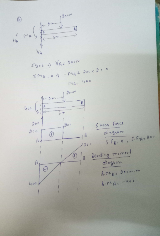
![2. [25 pts] Discuss the magnitude of the internal shear and moment along the length for each of the three cases shown. 200 N](http://img.homeworklib.com/questions/e8105140-1583-11ec-bdcb-f1bf3b927ab5.png?x-oss-process=image/resize,w_560)
Homework Answers

Add Answer to:
2. [25 pts] Discuss the magnitude of the internal shear and moment along the length for...
2 kip/It Problem 1 - Shear and Moment Diagrams (25 pts) The beam is bolted or...
 2 kip/It Problem 1 - Shear and Moment Diagrams (25 pts) The beam is bolted or pinned at A and rests on a bearing pad at B that exerts a uniform distributed loading on the beam over its 2-ft length. Draw the shear and moment diagrams for the beam if it supports a uniform loading of 2 kip/ft.. B 811 4.2 ft-
a) Find expressions for the shear force V and moment M at any point along the...
 a) Find expressions for the shear force V and moment M at any point along the beam shown below. b) Let x0 = 2L/3, what are the expressions for the shear force V and moment M at this location of beam AB in terms of peak load intensity 90 and beam length variable L. V, Matxo
Name: Question 6 (25 Points) For the shown beam below, determine the following: 1) The internal forces at F (mid-point between C & D) 2) Draw the Shear Force and Bending Moment diagrams ID: Sec:...
 Name: Question 6 (25 Points) For the shown beam below, determine the following: 1) The internal forces at F (mid-point between C & D) 2) Draw the Shear Force and Bending Moment diagrams ID: Sec: (9 Points) (16 Points) 20 N 100 N N/m
Name: Question 6 (25 Points) For the shown beam below, determine the following: 1) The internal forces at F (mid-point between C & D) 2) Draw the Shear Force and Bending Moment diagrams ID: Sec: (9...
Name: Question 6 (25 Points) For the shown beam below, determine the following: 1) The internal forces at F (mid-point between C & D) 2) Draw the Shear Force and Bending Moment diagrams ID: Sec: (9 Points) (16 Points) 20 N 100 N N/m
Name: Question 6 (25 Points) For the shown beam below, determine the following: 1) The internal forces at F (mid-point between C & D) 2) Draw the Shear Force and Bending Moment diagrams ID: Sec: (9...
Q3 (25 pts) 3. For the cantilever beam shown below and to the left, Determine the...
 Q3
(25 pts) 3. For the cantilever beam shown below and to the left, Determine the reactions at the wall at C. Draw the shear (V) and moment (M) diagram for the beam and label the appropriate values. For the given cross section, determine the magnitude of the maximum COMPRESSIVE bending stress and state where this occurs along the length of the beam and along the height of the beam (top or bottom). Sketch the NORMAL stress distribution (profile) for...
Q3
(25 pts) 3. For the cantilever beam shown below and to the left, Determine the reactions at the wall at C. Draw the shear (V) and moment (M) diagram for the beam and label the appropriate values. For the given cross section, determine the magnitude of the maximum COMPRESSIVE bending stress and state where this occurs along the length of the beam and along the height of the beam (top or bottom). Sketch the NORMAL stress distribution (profile) for...
The beam shown in (Figure 1) weighs 240 lb/ft. Find the magnitude of the internal normal force NC, the internal shear force VC, and the internal moment MC.
 The beam shown in (Figure 1) weighs 240 lb/ft. Find the
magnitude of the internal normal force NC, the internal
shear force VC, and the internal moment
MC.
The beam shown in (Figure 1) weighs 240 lb/ft. Find the
magnitude of the internal normal force NC, the internal
shear force VC, and the internal moment
MC.
3-55. Determine the required magnitude of force Fif the resultant couple moment on the frame is 2...
 3-55. Determine the required magnitude of force Fif the resultant couple moment on the frame is 200 N·m, clockwise. -0.2 m+0.2 m 30° 0.2 m 1500 N- 1500 N 0.2 m 30° 0.2 m
3-55. Determine the required magnitude of force Fif the resultant couple moment on the frame is 200 N·m, clockwise. -0.2 m+0.2 m 30° 0.2 m 1500 N- 1500 N 0.2 m 30° 0.2 m
3-55. Determine the required magnitude of force Fif the resultant couple moment on the frame is 200 N·m, clockwise. -0.2 m+0.2 m 30° 0.2 m 1500 N- 1500 N 0.2 m 30° 0.2 m
[25 points] Determine the magnitudes of the internal axial force, internal shear force, and internal bending...
 [25 points] Determine the magnitudes of the internal axial force, internal shear force, and internal bending moment at point C. Draw arrows to show the directions of the internal axial force, internal shear force, and internal bending moment at point C on both sketch. Label each arrow with its numerical value and units. Free- body diagrams and equilibrium equations are required 3. ←Ax 6 ft
1. Draw influence lines for shear and moment at 15, 25, and 30 feet from the left support for a simply supported be...
 1. Draw influence lines for shear and moment at 15, 25, and 30 feet from the left support for a simply supported beam with a span of 60 feet. Show values of maxima. 2. Using the influence lines in part 1, determine the shear and moment at 15, 25, and 30 feet for a uniformly distributed load of 50 k/ft applied over the length of the beam required to produce the maximum shear and moment at each point. 3. Using...
shear force and bending moment diagrams only. P4 (25 pts.) The top member of a gantry...
 shear force and bending moment diagrams only.
P4 (25 pts.) The top member of a gantry crane is made of three steel structural tubing as shown. The two end pieces are 3x3x 4 and the middle piece is 4x4x12. Generate the corresponding shear force and bending moment diagrams (by hand), and the slope and displacement of neutral axis (using the Excel spreadsheets provided to you). 1200 lb 10 18-10 /1200 b 4 X 4 x3 3 x3 x1 18 54...
shear force and bending moment diagrams only.
P4 (25 pts.) The top member of a gantry crane is made of three steel structural tubing as shown. The two end pieces are 3x3x 4 and the middle piece is 4x4x12. Generate the corresponding shear force and bending moment diagrams (by hand), and the slope and displacement of neutral axis (using the Excel spreadsheets provided to you). 1200 lb 10 18-10 /1200 b 4 X 4 x3 3 x3 x1 18 54...
1. Calculate the internal normal force at x=4.3 m in N. 2. Calculate the internal shear...
 1. Calculate the internal normal force at x=4.3 m in N.
2. Calculate the internal shear force at x=4.3m in N.
3. Calculate the internal bending moment at x=4.3 m in kN.m.
Problem 2 W M A 9 B 2 m 3 m 2 m 2 m W = 563 N/m M = 4.0 kN.m
1. Calculate the internal normal force at x=4.3 m in N.
2. Calculate the internal shear force at x=4.3m in N.
3. Calculate the internal bending moment at x=4.3 m in kN.m.
Problem 2 W M A 9 B 2 m 3 m 2 m 2 m W = 563 N/m M = 4.0 kN.m
 2 kip/It Problem 1 - Shear and Moment Diagrams (25 pts) The beam is bolted or pinned at A and rests on a bearing pad at B that exerts a uniform distributed loading on the beam over its 2-ft length. Draw the shear and moment diagrams for the beam if it supports a uniform loading of 2 kip/ft.. B 811 4.2 ft-
 a) Find expressions for the shear force V and moment M at any point along the beam shown below. b) Let x0 = 2L/3, what are the expressions for the shear force V and moment M at this location of beam AB in terms of peak load intensity 90 and beam length variable L. V, Matxo
 Name: Question 6 (25 Points) For the shown beam below, determine the following: 1) The internal forces at F (mid-point between C & D) 2) Draw the Shear Force and Bending Moment diagrams ID: Sec: (9 Points) (16 Points) 20 N 100 N N/m
Name: Question 6 (25 Points) For the shown beam below, determine the following: 1) The internal forces at F (mid-point between C & D) 2) Draw the Shear Force and Bending Moment diagrams ID: Sec: (9...
Name: Question 6 (25 Points) For the shown beam below, determine the following: 1) The internal forces at F (mid-point between C & D) 2) Draw the Shear Force and Bending Moment diagrams ID: Sec: (9 Points) (16 Points) 20 N 100 N N/m
Name: Question 6 (25 Points) For the shown beam below, determine the following: 1) The internal forces at F (mid-point between C & D) 2) Draw the Shear Force and Bending Moment diagrams ID: Sec: (9...
 Q3
(25 pts) 3. For the cantilever beam shown below and to the left, Determine the reactions at the wall at C. Draw the shear (V) and moment (M) diagram for the beam and label the appropriate values. For the given cross section, determine the magnitude of the maximum COMPRESSIVE bending stress and state where this occurs along the length of the beam and along the height of the beam (top or bottom). Sketch the NORMAL stress distribution (profile) for...
Q3
(25 pts) 3. For the cantilever beam shown below and to the left, Determine the reactions at the wall at C. Draw the shear (V) and moment (M) diagram for the beam and label the appropriate values. For the given cross section, determine the magnitude of the maximum COMPRESSIVE bending stress and state where this occurs along the length of the beam and along the height of the beam (top or bottom). Sketch the NORMAL stress distribution (profile) for...
 The beam shown in (Figure 1) weighs 240 lb/ft. Find the
magnitude of the internal normal force NC, the internal
shear force VC, and the internal moment
MC.
The beam shown in (Figure 1) weighs 240 lb/ft. Find the
magnitude of the internal normal force NC, the internal
shear force VC, and the internal moment
MC.
 3-55. Determine the required magnitude of force Fif the resultant couple moment on the frame is 200 N·m, clockwise. -0.2 m+0.2 m 30° 0.2 m 1500 N- 1500 N 0.2 m 30° 0.2 m
3-55. Determine the required magnitude of force Fif the resultant couple moment on the frame is 200 N·m, clockwise. -0.2 m+0.2 m 30° 0.2 m 1500 N- 1500 N 0.2 m 30° 0.2 m
3-55. Determine the required magnitude of force Fif the resultant couple moment on the frame is 200 N·m, clockwise. -0.2 m+0.2 m 30° 0.2 m 1500 N- 1500 N 0.2 m 30° 0.2 m
 [25 points] Determine the magnitudes of the internal axial force, internal shear force, and internal bending moment at point C. Draw arrows to show the directions of the internal axial force, internal shear force, and internal bending moment at point C on both sketch. Label each arrow with its numerical value and units. Free- body diagrams and equilibrium equations are required 3. ←Ax 6 ft
 1. Draw influence lines for shear and moment at 15, 25, and 30 feet from the left support for a simply supported beam with a span of 60 feet. Show values of maxima. 2. Using the influence lines in part 1, determine the shear and moment at 15, 25, and 30 feet for a uniformly distributed load of 50 k/ft applied over the length of the beam required to produce the maximum shear and moment at each point. 3. Using...
 shear force and bending moment diagrams only.
P4 (25 pts.) The top member of a gantry crane is made of three steel structural tubing as shown. The two end pieces are 3x3x 4 and the middle piece is 4x4x12. Generate the corresponding shear force and bending moment diagrams (by hand), and the slope and displacement of neutral axis (using the Excel spreadsheets provided to you). 1200 lb 10 18-10 /1200 b 4 X 4 x3 3 x3 x1 18 54...
shear force and bending moment diagrams only.
P4 (25 pts.) The top member of a gantry crane is made of three steel structural tubing as shown. The two end pieces are 3x3x 4 and the middle piece is 4x4x12. Generate the corresponding shear force and bending moment diagrams (by hand), and the slope and displacement of neutral axis (using the Excel spreadsheets provided to you). 1200 lb 10 18-10 /1200 b 4 X 4 x3 3 x3 x1 18 54...
 1. Calculate the internal normal force at x=4.3 m in N.
2. Calculate the internal shear force at x=4.3m in N.
3. Calculate the internal bending moment at x=4.3 m in kN.m.
Problem 2 W M A 9 B 2 m 3 m 2 m 2 m W = 563 N/m M = 4.0 kN.m
1. Calculate the internal normal force at x=4.3 m in N.
2. Calculate the internal shear force at x=4.3m in N.
3. Calculate the internal bending moment at x=4.3 m in kN.m.
Problem 2 W M A 9 B 2 m 3 m 2 m 2 m W = 563 N/m M = 4.0 kN.m
Most questions answered within 3 hours.
-
Write a program to solve the Josephus problem, with the following
modification:
Sample Input:
./a.out n...
asked 2 hours ago -
At the start of a CD it is spinning at a rate of 525 rpm
(revolutions...
asked 2 hours ago -
4. Without doing any calculations, predict whether the observed
∆T would increase, decrease or remain the...
asked 4 hours ago -
Based on the range, which of the following sets of scores has
the greatest variability? 3,...
asked 5 hours ago -
Ripples in a pond travel at a velocity of 3 m/s with one peak
passing a...
asked 5 hours ago -
A man stands on the roof of a building of height 13.0 mm and
throws a...
asked 5 hours ago -
The extent to which assets are financed by borrowed funds and
other liabilities is indicated by:...
asked 6 hours ago -
Explain in detail
Germany is the fifth largest economy
explain what goods and services Germany specializes...
asked 6 hours ago -
The density of platinum is 21.45 g/mL. If a cube of platinum
with a mass of...
asked 6 hours ago -
Accounts Receivable
Sales
A/R Posting
Extended Sales Invoice
Packing Slip
Compare invoice to packing slip 2...
asked 6 hours ago -
Michaella, age 23, is a full-time law student and is claimed by
her parents as a...
asked 6 hours ago -
Why are polymers not typically casted into products?
asked 6 hours ago