
Homework Answers
Answer:
given the

Add Answer to:
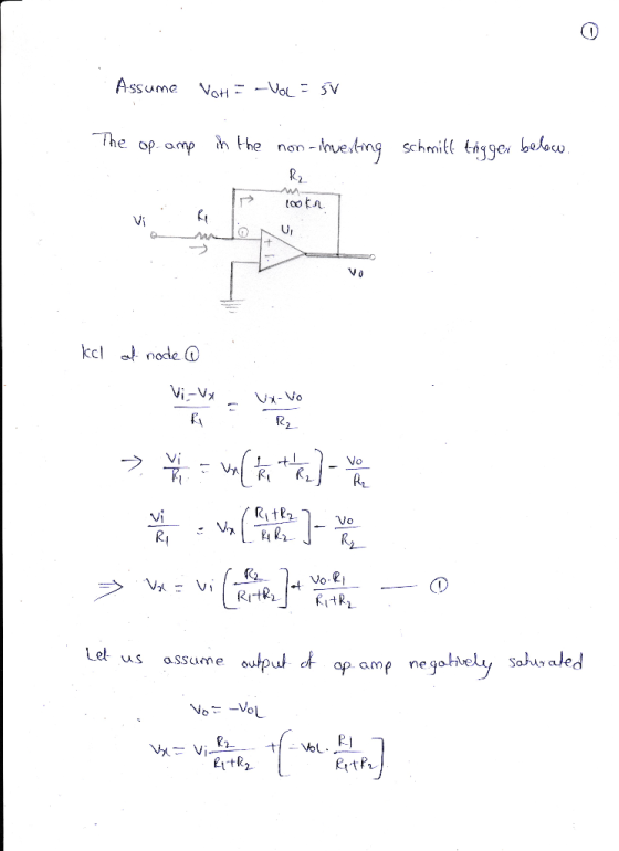
For the op-amp in the non-inverting Schmitt trigger below, assume VoH = -VOL = 5V. Determine...
Design 1. Design a non-inverting Schmitt Trigger with switching points of VHL 0V and VH 5V...
 Design 1. Design a non-inverting Schmitt Trigger with switching points of VHL 0V and VH 5V 2. Design an op-amp integrator that uses no more than 1mA of input current and changes its output by 5V in 10usec when driven by the Schmitt Trigger designed in (1) When the integrator is connected to the Schmitt Trigger in the feedback arrangement below it will produce a relaxation oscillator that outputs a 5V triangle wave with a frequency of 50kHz. +9V C1...
(a) Design a inverting Schmitt trigger circuit to be used as a zero crossing detector with transition voltages about ±25...
 (a) Design a inverting Schmitt trigger circuit
to be used as a zero crossing detector with transition voltages
about ±25 mV. Assume the saturation voltages for the op–amp are ±13
V. Draw the voltage transfer characteristic (VTC), i.e., vout vs.
vin.
(b) Design an astable multivibrator to produce
a square signal with a frequency of 1 kHz using C=0.01 µF, R1 = 30
kΩ, and R2 = 20 kΩ. Sketch the circuit waveforms (vo, v +, and v −)
assuming...
(a) Design a inverting Schmitt trigger circuit
to be used as a zero crossing detector with transition voltages
about ±25 mV. Assume the saturation voltages for the op–amp are ±13
V. Draw the voltage transfer characteristic (VTC), i.e., vout vs.
vin.
(b) Design an astable multivibrator to produce
a square signal with a frequency of 1 kHz using C=0.01 µF, R1 = 30
kΩ, and R2 = 20 kΩ. Sketch the circuit waveforms (vo, v +, and v −)
assuming...
4. A non-inverting amplifier shown below is to be constructed with a uA741C Op. Amp. It...
 4. A non-inverting amplifier shown below is to be constructed with a uA741C Op. Amp. It is to have a gain of 1001 with R1=100 ohms. Assume the GBP (non- inverting) = 100 kHz (a) Specify value of the resistor R2. (b) Sketch the Bode plot for this amplifier using specific numerical values and indicate the cut-off frequency. R R1 B Op-amp + +o VO TH
4. A non-inverting amplifier shown below is to be constructed with a uA 741C Op. Amp....
 4. A non-inverting amplifier shown below is to be constructed with a uA 741C Op. Amp. It is to have a gain of 1001 with R1=100 ohms. Assume the GBP (non- inverting) = 100 kHz (a) Specify value of the resistor R2. (b) Sketch the Bode plot for this amplifier using specific numerical values and indicate the cut-off frequency. R2 R w B Op-amp + + o V HU TH
For the driven-right-leg system below along with its equivalent circuit, assume 4. R,-5M0(non-ideal input impedance of op-amp) db Rx Auxiliary op amp RL db R1 Vcm_ Vi R5 2 RF R4 Rx o v RG 0 7 RA Aux...
 For the driven-right-leg system below along with its equivalent circuit, assume 4. R,-5M0(non-ideal input impedance of op-amp) db Rx Auxiliary op amp RL db R1 Vcm_ Vi R5 2 RF R4 Rx o v RG 0 7 RA Auxiliary Amplifier O VREF 2 R2 What are the benefits of using the driven-right-leg circuit? What is the value of the common-mode voltage if resistor RRL is tied to ground instead of the auxiliary amplifier? e.
For the driven-right-leg system below along...
For the driven-right-leg system below along with its equivalent circuit, assume 4. R,-5M0(non-ideal input impedance of op-amp) db Rx Auxiliary op amp RL db R1 Vcm_ Vi R5 2 RF R4 Rx o v RG 0 7 RA Auxiliary Amplifier O VREF 2 R2 What are the benefits of using the driven-right-leg circuit? What is the value of the common-mode voltage if resistor RRL is tied to ground instead of the auxiliary amplifier? e.
For the driven-right-leg system below along...
 Design 1. Design a non-inverting Schmitt Trigger with switching points of VHL 0V and VH 5V 2. Design an op-amp integrator that uses no more than 1mA of input current and changes its output by 5V in 10usec when driven by the Schmitt Trigger designed in (1) When the integrator is connected to the Schmitt Trigger in the feedback arrangement below it will produce a relaxation oscillator that outputs a 5V triangle wave with a frequency of 50kHz. +9V C1...
 (a) Design a inverting Schmitt trigger circuit
to be used as a zero crossing detector with transition voltages
about ±25 mV. Assume the saturation voltages for the op–amp are ±13
V. Draw the voltage transfer characteristic (VTC), i.e., vout vs.
vin.
(b) Design an astable multivibrator to produce
a square signal with a frequency of 1 kHz using C=0.01 µF, R1 = 30
kΩ, and R2 = 20 kΩ. Sketch the circuit waveforms (vo, v +, and v −)
assuming...
(a) Design a inverting Schmitt trigger circuit
to be used as a zero crossing detector with transition voltages
about ±25 mV. Assume the saturation voltages for the op–amp are ±13
V. Draw the voltage transfer characteristic (VTC), i.e., vout vs.
vin.
(b) Design an astable multivibrator to produce
a square signal with a frequency of 1 kHz using C=0.01 µF, R1 = 30
kΩ, and R2 = 20 kΩ. Sketch the circuit waveforms (vo, v +, and v −)
assuming...
 4. A non-inverting amplifier shown below is to be constructed with a uA741C Op. Amp. It is to have a gain of 1001 with R1=100 ohms. Assume the GBP (non- inverting) = 100 kHz (a) Specify value of the resistor R2. (b) Sketch the Bode plot for this amplifier using specific numerical values and indicate the cut-off frequency. R R1 B Op-amp + +o VO TH
 4. A non-inverting amplifier shown below is to be constructed with a uA 741C Op. Amp. It is to have a gain of 1001 with R1=100 ohms. Assume the GBP (non- inverting) = 100 kHz (a) Specify value of the resistor R2. (b) Sketch the Bode plot for this amplifier using specific numerical values and indicate the cut-off frequency. R2 R w B Op-amp + + o V HU TH
 4. A non-inverting amplifier shown below is to be constructed with a uA 741C Op. Amp. It is to have a gain of 1001 with R1=100 ohms. Assume the GBP (non- inverting) = 100 kHz (a) Specify value of the resistor R2. (b) Sketch the Bode plot for this amplifier using specific numerical values and indicate the cut-off frequency. R2 R w B Op-amp + + o V HU TH
 For the driven-right-leg system below along with its equivalent circuit, assume 4. R,-5M0(non-ideal input impedance of op-amp) db Rx Auxiliary op amp RL db R1 Vcm_ Vi R5 2 RF R4 Rx o v RG 0 7 RA Auxiliary Amplifier O VREF 2 R2 What are the benefits of using the driven-right-leg circuit? What is the value of the common-mode voltage if resistor RRL is tied to ground instead of the auxiliary amplifier? e.
For the driven-right-leg system below along...
For the driven-right-leg system below along with its equivalent circuit, assume 4. R,-5M0(non-ideal input impedance of op-amp) db Rx Auxiliary op amp RL db R1 Vcm_ Vi R5 2 RF R4 Rx o v RG 0 7 RA Auxiliary Amplifier O VREF 2 R2 What are the benefits of using the driven-right-leg circuit? What is the value of the common-mode voltage if resistor RRL is tied to ground instead of the auxiliary amplifier? e.
For the driven-right-leg system below along...
Most questions answered within 3 hours.
-
The marketing class at CSUS had an average score of 150. An
educational analyst determined that...
asked 1 hour ago -
Justin Case has purchased a $250 000 home by putting 20 % down
and taking out...
asked 1 hour ago -
1. In a labor market, marginal cost for a firm is
____________.
a. recruiting cost
b....
asked 1 hour ago -
On January 1, 2019, ABC Company issued $60,000,000 of 20-year,
10.5% bonds when the market rate...
asked 2 hours ago -
39.4% of US homes continue to use a landline in addition to cell
phone service. 3...
asked 2 hours ago -
Starting with benzene, synthesize 1-phenyl-1-butyne.
Show intermediates and reagents.
asked 3 hours ago -
Create a 32-run crossed array design with six control factors
and two noise factors such that...
asked 4 hours ago -
A 500g sample of sand from source A has the following amounts
retained on each sieve....
asked 4 hours ago -
In
your own words, please explain the essay by John Keynes wrote "The
End of Laissez...
asked 4 hours ago -
How are the matrix and pixels related? Why are smaller
pixels better for diagnostic quality?
asked 4 hours ago -
2. An AC generator has 80 rectangular loops on
its armature. Each loop is 11 cm...
asked 4 hours ago -
Please help me with this question. Consider Aldi’s current and
potential geographic markets (see Exhibit 4...
asked 4 hours ago