Homework Answers
Request Answer!
We need at least 10 more requests to produce the answer.
0 / 10 have requested this problem solution
The more requests, the faster the answer.
Add Answer to:
Please use correct units
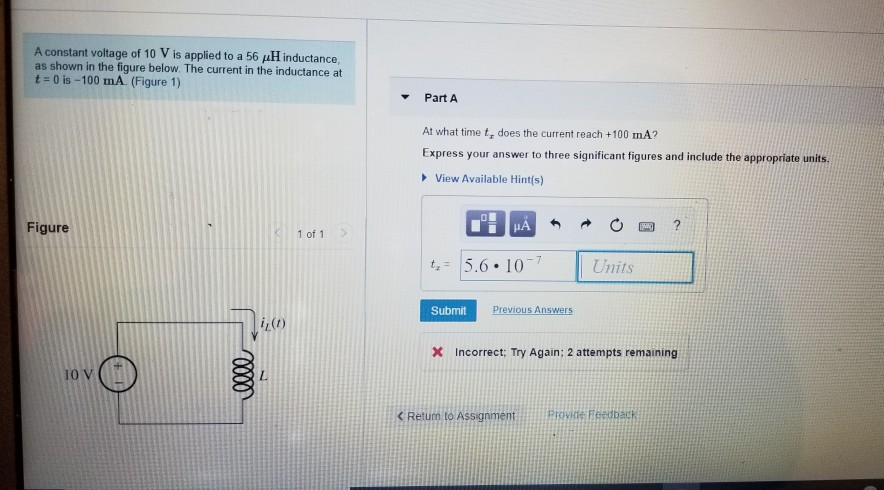
A constant voltage of 10 V is applied to a 56 pH...
The current shown in (Figure 1) is applied to a 600 nF capacitor. The initial voltage...
 The current shown in (Figure 1) is applied to a 600 nF capacitor. The initial voltage on the capacitor is zero. Part A Find the charge on the capacitor at t = 30 us. Express your answer to three significant figures and include the appropriate units. 4 = 4.50 C Submit Previous Answers Correct Part B Find the voltage on the capacitor at t = 50 js. Express your answer to three significant figures and include the appropriate units. HA...
Problem 4.23 - Enhanced - with Hints and Feedback Use the node-voltage method to find the...
 Problem 4.23 - Enhanced - with Hints and Feedback Use the node-voltage method to find the branch currents i1.12, and is in the circuit in (Figure 1) if uy = 40 V and v3 = 75 V Part A Find the current i Express your answer to three significant figures and include the appropriate units. View Available Hint(s) HA ? 0.87 mA Submit Previous Answers X Incorrect; Try Again; 5 attempts remaining Part B Find the current i Express your...
The current i, in the circuit shown in (Figura 1), is 90 mA and the voltage...
 The current i, in the circuit shown in (Figura 1), is 90 mA and the voltage , is 630 V Part A Determine the current Express your answer to three significant figures and include the appropriate units. 1 - 35.0 mA Previous AUS Correct Part B Determine the voltage Express your answer to three significant figures and include the appropriate units. - 13.5 V Suomi Previous Answers ✓ Correct Part Determine the voltage 1 Express your answer to three significant...
Review Constants The current shown in (Figure 1) is applied to a 350 nF capacitor. The...
 Review Constants The current shown in (Figure 1) is applied to a 350 nF capacitor. The initial voltage on the capacitor is zero. Part A Find the charge on the capacitor at t = 30 jus Express your answer to three significant figures and include the appropriate units. IT μΑ q= 25.103 O Submit Previous Answers Request Answer Part B Find the voltage on the capacitor at t = 50 js. Express your answer to three significant figures and include...
Problem 26.44 13 of 14 Part A Constants | Periodic Table In the figure, the total resistance is 12.8 k2, and the battery's emf is 28.8 V.If the time constant is measured to be 23.0148 Figure 1) C...
 Problem 26.44 13 of 14 Part A Constants | Periodic Table In the figure, the total resistance is 12.8 k2, and the battery's emf is 28.8 V.If the time constant is measured to be 23.0148 Figure 1) Calculate the total capacitance of the circuit. C 1.80x10⁹ F Correct Part B Calculate the time it takes for the voltage across the resistor to reach 17.6 V after the switch is closed. Figure 1 of 1 Submit X Incorrect, Try Again; 4...
Problem 3.28 PSpicelMultisim Part A Find the voltage v in the circuit in the figure, if...
 Problem 3.28 PSpicelMultisim Part A Find the voltage v in the circuit in the figure, if V-18 V.(Figure 1) Express your answer to two significant figures and include the appropriate units. Uz =1 Value Units Submit Previous Answers Request Answer Figure 1 of 1 X Incorrect; Try Again; 10 attempts remaining Part B Complete previous part(s) 2 k2 Provide Feedback
In the circuit below, the voltage supplied by the power source is 10 V and the...
 In the circuit below, the voltage supplied by the power source
is 10 V and the current flowing through the circuit is 0.12
A.
KE3 Prelaboratory Questions E3 - Question 1: Resistance in a Circuit 1 of 5 Review 1 Constants i Periodic Table Part A In the circuit below, the voltage supplied by the power source is 10 V and the current flowing through the circuit is 0.12 A What is the resistance R2? 35 S2 33.75 Submit Previous...
In the circuit below, the voltage supplied by the power source
is 10 V and the current flowing through the circuit is 0.12
A.
KE3 Prelaboratory Questions E3 - Question 1: Resistance in a Circuit 1 of 5 Review 1 Constants i Periodic Table Part A In the circuit below, the voltage supplied by the power source is 10 V and the current flowing through the circuit is 0.12 A What is the resistance R2? 35 S2 33.75 Submit Previous...
PLEASE BOX ALL ANSWERS FOR A THUMBS UP Problem 6.34 - Enhanced - with Hints and...
 PLEASE BOX ALL ANSWERS FOR A THUMBS UP
Problem 6.34 - Enhanced - with Hints and Feedback At t=0, a series-connected capacitor and inductor are placed across the terminals of a black box as shown in (Figure 1). For t > 0, it is known that in = 1.5e -16,000+ - 0.5e-40006 A, where t is in seconds. Part A If vc(0) = -50 V, choose the correct expression for vo fort > 0. View Available Hint(s) Vo = 750e...
PLEASE BOX ALL ANSWERS FOR A THUMBS UP
Problem 6.34 - Enhanced - with Hints and Feedback At t=0, a series-connected capacitor and inductor are placed across the terminals of a black box as shown in (Figure 1). For t > 0, it is known that in = 1.5e -16,000+ - 0.5e-40006 A, where t is in seconds. Part A If vc(0) = -50 V, choose the correct expression for vo fort > 0. View Available Hint(s) Vo = 750e...
The sinusoidal voltage source in the circuit shown in Figure 1) is generating the voltage ,...
 The sinusoidal voltage source in the circuit shown in Figure 1) is generating the voltage , 4cos 2000 V. The op amp is ideal Write the steady-state expression for v.() as vo(t) =V, cos(wt + ), where -180 < < 180° Suppose that R = 45 k2 Express your answer to three significant figures and include the appropriate units. ► View Available Hint(s) "! A V. - 0.812 RO? V Submit Previous Answers * Incorrect; Try Again; 9 attempts remaining...
Problem 9.14 2 of 13 Review I Constants The expressions for the steady-state voltage and current...
 Problem 9.14 2 of 13 Review I Constants The expressions for the steady-state voltage and current at the terminals of the circuit seen in the figure are g 350 cos(5000xt85°) V, ig=8 sin(5000rt 108°) A (Figure 1) Part A What is the impedance seen by the source? Express your answer in ohms to three significant figures using polar notation. Express argument in degrees. VA D T vec Z=43.75 27 Ω Previous Answers Request Answer Submit Incorrect; Try Again; 3 attempts...
 The current shown in (Figure 1) is applied to a 600 nF capacitor. The initial voltage on the capacitor is zero. Part A Find the charge on the capacitor at t = 30 us. Express your answer to three significant figures and include the appropriate units. 4 = 4.50 C Submit Previous Answers Correct Part B Find the voltage on the capacitor at t = 50 js. Express your answer to three significant figures and include the appropriate units. HA...
 Problem 4.23 - Enhanced - with Hints and Feedback Use the node-voltage method to find the branch currents i1.12, and is in the circuit in (Figure 1) if uy = 40 V and v3 = 75 V Part A Find the current i Express your answer to three significant figures and include the appropriate units. View Available Hint(s) HA ? 0.87 mA Submit Previous Answers X Incorrect; Try Again; 5 attempts remaining Part B Find the current i Express your...
 The current i, in the circuit shown in (Figura 1), is 90 mA and the voltage , is 630 V Part A Determine the current Express your answer to three significant figures and include the appropriate units. 1 - 35.0 mA Previous AUS Correct Part B Determine the voltage Express your answer to three significant figures and include the appropriate units. - 13.5 V Suomi Previous Answers ✓ Correct Part Determine the voltage 1 Express your answer to three significant...
 Review Constants The current shown in (Figure 1) is applied to a 350 nF capacitor. The initial voltage on the capacitor is zero. Part A Find the charge on the capacitor at t = 30 jus Express your answer to three significant figures and include the appropriate units. IT μΑ q= 25.103 O Submit Previous Answers Request Answer Part B Find the voltage on the capacitor at t = 50 js. Express your answer to three significant figures and include...
 Problem 26.44 13 of 14 Part A Constants | Periodic Table In the figure, the total resistance is 12.8 k2, and the battery's emf is 28.8 V.If the time constant is measured to be 23.0148 Figure 1) Calculate the total capacitance of the circuit. C 1.80x10⁹ F Correct Part B Calculate the time it takes for the voltage across the resistor to reach 17.6 V after the switch is closed. Figure 1 of 1 Submit X Incorrect, Try Again; 4...
 Problem 3.28 PSpicelMultisim Part A Find the voltage v in the circuit in the figure, if V-18 V.(Figure 1) Express your answer to two significant figures and include the appropriate units. Uz =1 Value Units Submit Previous Answers Request Answer Figure 1 of 1 X Incorrect; Try Again; 10 attempts remaining Part B Complete previous part(s) 2 k2 Provide Feedback
 In the circuit below, the voltage supplied by the power source
is 10 V and the current flowing through the circuit is 0.12
A.
KE3 Prelaboratory Questions E3 - Question 1: Resistance in a Circuit 1 of 5 Review 1 Constants i Periodic Table Part A In the circuit below, the voltage supplied by the power source is 10 V and the current flowing through the circuit is 0.12 A What is the resistance R2? 35 S2 33.75 Submit Previous...
In the circuit below, the voltage supplied by the power source
is 10 V and the current flowing through the circuit is 0.12
A.
KE3 Prelaboratory Questions E3 - Question 1: Resistance in a Circuit 1 of 5 Review 1 Constants i Periodic Table Part A In the circuit below, the voltage supplied by the power source is 10 V and the current flowing through the circuit is 0.12 A What is the resistance R2? 35 S2 33.75 Submit Previous...
 PLEASE BOX ALL ANSWERS FOR A THUMBS UP
Problem 6.34 - Enhanced - with Hints and Feedback At t=0, a series-connected capacitor and inductor are placed across the terminals of a black box as shown in (Figure 1). For t > 0, it is known that in = 1.5e -16,000+ - 0.5e-40006 A, where t is in seconds. Part A If vc(0) = -50 V, choose the correct expression for vo fort > 0. View Available Hint(s) Vo = 750e...
PLEASE BOX ALL ANSWERS FOR A THUMBS UP
Problem 6.34 - Enhanced - with Hints and Feedback At t=0, a series-connected capacitor and inductor are placed across the terminals of a black box as shown in (Figure 1). For t > 0, it is known that in = 1.5e -16,000+ - 0.5e-40006 A, where t is in seconds. Part A If vc(0) = -50 V, choose the correct expression for vo fort > 0. View Available Hint(s) Vo = 750e...
 The sinusoidal voltage source in the circuit shown in Figure 1) is generating the voltage , 4cos 2000 V. The op amp is ideal Write the steady-state expression for v.() as vo(t) =V, cos(wt + ), where -180 < < 180° Suppose that R = 45 k2 Express your answer to three significant figures and include the appropriate units. ► View Available Hint(s) "! A V. - 0.812 RO? V Submit Previous Answers * Incorrect; Try Again; 9 attempts remaining...
 Problem 9.14 2 of 13 Review I Constants The expressions for the steady-state voltage and current at the terminals of the circuit seen in the figure are g 350 cos(5000xt85°) V, ig=8 sin(5000rt 108°) A (Figure 1) Part A What is the impedance seen by the source? Express your answer in ohms to three significant figures using polar notation. Express argument in degrees. VA D T vec Z=43.75 27 Ω Previous Answers Request Answer Submit Incorrect; Try Again; 3 attempts...
Most questions answered within 3 hours.
-
in
a certain experiment 5.280 g of hydrochloric acid (HCl) reacts with
excess calcium carbonate (CaCO3)....
asked 1 second ago -
Suppose that a competitive firm’s MC = 3 + 2q, AVC = 3 + q, and...
asked 4 minutes ago -
When I invoke the forward or backward method the current_number
isnt being changed. Not sure if...
asked 5 minutes ago -
At the Pinelands University Medical Center, clinics trials were
performed with a medical treatment intended to...
asked 18 minutes ago -
Question 1.
XOR
Challenge 1: The key is a single digit
Decrypt the cipher =
snw{fzs...
asked 24 minutes ago -
Propose the importance of the financial account (from the BOP)
to economic indicators.?
asked 20 minutes ago -
Please submit the following files for this
assignment:
**************************Animal.h, Animal.cpp,
Mammal.h, Mammal.cpp, Cat.h, Cat.cpp,
main.cpp********************************************************
Assignment...
asked 21 minutes ago -
Multidimensional arrays can be stored in row major order or in
column major order. The access...
asked 23 minutes ago -
A study is conducted
to determine the simple linear regression relation (if any) between
average temperature...
asked 41 minutes ago -
Twenty percent of all telephones of a certain type are submitted
for service while under warranty....
asked 1 hour ago -
Which is a method of transmitting pathogens from one host to
another by carrying microorganisms inside...
asked 51 minutes ago -
In a memo written to a US trade policy maker, outline an
argument for the role...
asked 43 minutes ago