
Homework Answers


Add Answer to:
(18 pts) 10. Consider the circuit shown in the sketch. R1-30 Ω, R,- 2, and Ra...
Consider the circuit shown below. Where R1 = 30 Ω , R2 = 40 Ω ,...
 Consider the circuit shown below. Where R1 = 30 Ω , R2 = 40 Ω ,
and R3 = 90 Ω . When a battery with unknown voltage is hooked up
between points A and B, the current through the resistor R1 is I1
= 0.050 A
What is the voltage across R3? What is the current through the
resistor R3?
What is the total current produced by the battery hooked between
points A and B?
What is the voltage...
Consider the circuit shown below. Where R1 = 30 Ω , R2 = 40 Ω ,
and R3 = 90 Ω . When a battery with unknown voltage is hooked up
between points A and B, the current through the resistor R1 is I1
= 0.050 A
What is the voltage across R3? What is the current through the
resistor R3?
What is the total current produced by the battery hooked between
points A and B?
What is the voltage...
Review In the circuit shown in the diagram(Figure 1), suppose R1=R2 = 220 Ω and R3=R....
Review In the circuit shown in the diagram(Figure 1), suppose R1=R2 = 220 Ω and R3=R. The emf of the battery is 12.0 V . (A)Find the value of R such that the current supplied by the battery is 0.0900 A . (B)Find the value of R that gives a potential difference of 4.35 V across resistor 2.
Consider the circuit shown in the figure below. (Assume R1 = 12.0 Ω and R2 = 7.00 Ω.)
 Consider the circuit shown in the figure below. (Assume R1 = 12.0 Ω and R2 = 7.00 Ω.)(a) Find the potential difference between points a and b. (b) Find the current in the 20.0-Ω resistor.
(17 pts) 15. In the series RLC circuit shown in the sketch, R = 80.0 Ω,...
 (17 pts) 15. In the series RLC circuit shown in the sketch, R = 80.0 Ω, L-0.600 H, c-200x10-5 F and the volage source has angular frequency o 250 rad/s. The voltage amplitude for the resistor is 40.0 V. a) What is the voltage amplitude for the inductor? Ans b) What is the voltage amplitude of the source? Ans c) Does the source voltage lag or lead the current? Ans d) At what 'rate does the voltage source supply electrical...
Consider the circuit shown in the figure below. (Assume R1 = 15.5 Ω and R2 =...
 Consider the circuit shown in the figure below. (Assume
R1 = 15.5 Ω and R2 = 4.50
Ω.)
(a) Find the potential difference between points a and
b.
V
(b) Find the current in the 20.0-Ω resistor.
A
Consider the circuit shown in the figure below. (Assume
R1 = 15.5 Ω and R2 = 4.50
Ω.)
(a) Find the potential difference between points a and
b.
V
(b) Find the current in the 20.0-Ω resistor.
A
Consider the circuit shown in the figure below. (Assume R1: 11.0 Ω and R,-8.00 Ω.) 25.0...
 Consider the circuit shown in the figure below. (Assume R1: 11.0 Ω and R,-8.00 Ω.) 25.0 V Ri Ri 20.0 Ω (a) Find the potential difference between points a and b. Your response differs from the correct answer by more than 100%. V (b) Find the current in the 20.0-2 resistor
Let RC = 50 Ω, RB = 61 Ω, RA = 70 Ω and the Potential...
Let RC = 50 Ω, RB = 61 Ω, RA = 70 Ω and the Potential Difference of the battery be 104 V a.Given the circuit above find the potential difference across and Current through each resistor. b. How much Power is Resistor B using? Watts c. How much Power is the Whole circuit using? Watts d.RA is a variable transistor that can be adjusted between 50 Ω and 100 Ω. What should the A be adjusted to if you want the...
3. Equivalent Resistance (20 pts) 222-152C The resistors in the figure have the following R1 ....
 3. Equivalent Resistance (20 pts) 222-152C The resistors in the figure have the following R1 . values o Ritz 25.0 Ω o R2-45.0 Ω o R3 15.0 Ω R4-35.0 Ω Rs. 10.0 Ω R6- 55.0 2 R2 Ra The emf device shown supplies 20 V to the circuit. (a) Find the equivalent resistance of this circuit. (b) Find the current and direction of current flow through R3. (c) Find the potential difference, Vab, across points a and b. Solution: ....
12. 10 points KnightCP1 23.P060. Consider the circuit shown in the figure below, in which RA...
 12. 10 points KnightCP1 23.P060. Consider the circuit shown in the figure below, in which RA = 27 Ω and RB = 11 Ω. Tabulate the current through, and the potential difference across, each resistor. 412 6Ω 24 V B 24 Ω resistor current (A) potential difference (V) 49 RA (2752) 6Ω Ag (11 Ω) 24 Ω
QUESTION 6 In the circuit shown in the figure below R1 . 3.8 Ω R2·6 Ω...
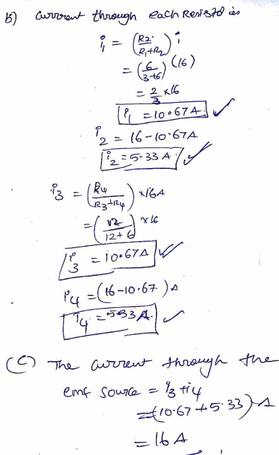
 QUESTION 6 In the circuit shown in the figure below R1 . 3.8 Ω R2·6 Ω R3 2.8 Ω 11 . 3.1 A 12 5.4 Aand -1 9 A Calculate the po er produced or consumed y the emf2 (Give your answer in algebraic decimal: (+) if the emf produces electrical power and () of the emf consumes electrical power. Use "W" as unit) e1 e2 Ry QUESTION 7 In the circuit shown in the figure below ε1-8 V and...
 Consider the circuit shown below. Where R1 = 30 Ω , R2 = 40 Ω ,
and R3 = 90 Ω . When a battery with unknown voltage is hooked up
between points A and B, the current through the resistor R1 is I1
= 0.050 A
What is the voltage across R3? What is the current through the
resistor R3?
What is the total current produced by the battery hooked between
points A and B?
What is the voltage...
Consider the circuit shown below. Where R1 = 30 Ω , R2 = 40 Ω ,
and R3 = 90 Ω . When a battery with unknown voltage is hooked up
between points A and B, the current through the resistor R1 is I1
= 0.050 A
What is the voltage across R3? What is the current through the
resistor R3?
What is the total current produced by the battery hooked between
points A and B?
What is the voltage...
 (17 pts) 15. In the series RLC circuit shown in the sketch, R = 80.0 Ω, L-0.600 H, c-200x10-5 F and the volage source has angular frequency o 250 rad/s. The voltage amplitude for the resistor is 40.0 V. a) What is the voltage amplitude for the inductor? Ans b) What is the voltage amplitude of the source? Ans c) Does the source voltage lag or lead the current? Ans d) At what 'rate does the voltage source supply electrical...
 Consider the circuit shown in the figure below. (Assume
R1 = 15.5 Ω and R2 = 4.50
Ω.)
(a) Find the potential difference between points a and
b.
V
(b) Find the current in the 20.0-Ω resistor.
A
Consider the circuit shown in the figure below. (Assume
R1 = 15.5 Ω and R2 = 4.50
Ω.)
(a) Find the potential difference between points a and
b.
V
(b) Find the current in the 20.0-Ω resistor.
A
 Consider the circuit shown in the figure below. (Assume R1: 11.0 Ω and R,-8.00 Ω.) 25.0 V Ri Ri 20.0 Ω (a) Find the potential difference between points a and b. Your response differs from the correct answer by more than 100%. V (b) Find the current in the 20.0-2 resistor
 3. Equivalent Resistance (20 pts) 222-152C The resistors in the figure have the following R1 . values o Ritz 25.0 Ω o R2-45.0 Ω o R3 15.0 Ω R4-35.0 Ω Rs. 10.0 Ω R6- 55.0 2 R2 Ra The emf device shown supplies 20 V to the circuit. (a) Find the equivalent resistance of this circuit. (b) Find the current and direction of current flow through R3. (c) Find the potential difference, Vab, across points a and b. Solution: ....
 12. 10 points KnightCP1 23.P060. Consider the circuit shown in the figure below, in which RA = 27 Ω and RB = 11 Ω. Tabulate the current through, and the potential difference across, each resistor. 412 6Ω 24 V B 24 Ω resistor current (A) potential difference (V) 49 RA (2752) 6Ω Ag (11 Ω) 24 Ω
 QUESTION 6 In the circuit shown in the figure below R1 . 3.8 Ω R2·6 Ω R3 2.8 Ω 11 . 3.1 A 12 5.4 Aand -1 9 A Calculate the po er produced or consumed y the emf2 (Give your answer in algebraic decimal: (+) if the emf produces electrical power and () of the emf consumes electrical power. Use "W" as unit) e1 e2 Ry QUESTION 7 In the circuit shown in the figure below ε1-8 V and...
Most questions answered within 3 hours.
-
there is a function to create two random numbers between 1 and
25 and a function...
asked 15 minutes ago -
At a certain temperature, the ?pKp for the decomposition of
H2SH2S is 0.832.0.832.
H2S(g)↽−−⇀H2(g)+S(g)H2S(g)↽−−⇀H2(g)+S(g)
Initially, only...
asked 9 minutes ago -
Part 1.C&A Fast Food has four activities in serving a
customer: greet customer, take order, process...
asked 15 minutes ago -
Which attribute allows you to specify a custom "thumbnail" for
multimedia elements?
asked 54 minutes ago -
How much 0.1200 M sodium hydroxide solution is need to titrate
14 mL of a 0.100...
asked 29 minutes ago -
An impulse is a change in momentum usually over
a short time. For which of the...
asked 34 minutes ago -
1a)When a 5000-kg roller coaster train full of riders approaches
the loading dock at a speed...
asked 54 minutes ago -
The Poseidon Swim Company produces swim trunks. The average
selling price for one of their swim...
asked 49 minutes ago -
If the elasticity of supply of a good is ∞, then its
A. supply curve is...
asked 35 minutes ago -
Write an application for the Shady Rest Hotel; the program
determines the price of a room....
asked 40 minutes ago -
USE THE FOLLOWING INFORMATION TO ANSWER THE NEXT (6)
QUESTIONS:
The following is a December 31,...
asked 56 minutes ago -
Suppose you plan to invest $5,000 each year (beginning at the
end of this year) into...
asked 46 minutes ago