

Homework Answers
Solution:
If you found this solution useful then please upvote
for any query please comment
Thank you,.


Add Answer to:
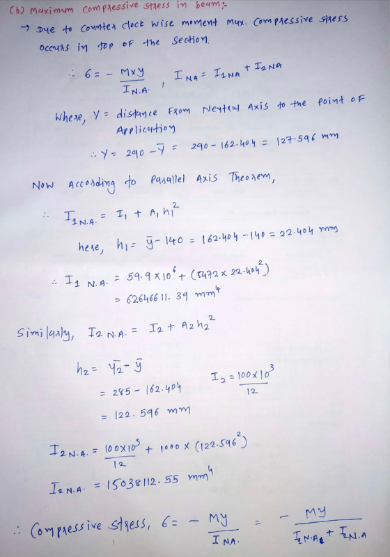
Figure 1 shows A fully symmetrical I beam of area A1 = 5472 mm?, and second...
e = 108.3 mm A = 10 Ixx = 162.2 2. Figure Q.2 shows the section of a symmetrical prestressed concrete beam in which the eccentricity of the tendons is e mm, the cross-section area is A x 10 (mm',...
 e = 108.3 mm
A = 10
Ixx = 162.2
2. Figure Q.2 shows the section of a symmetrical prestressed concrete beam in which the eccentricity of the tendons is e mm, the cross-section area is A x 10 (mm', and the 2d moment of area about x-x axis is Iux x 10' (mm). (50%) Figure Q.2 240 Calculate the maximum allowable prestressing force if, at the prestressing stage, the allowable stresses are 1 N/mm2 tension and 20 N/mn2 compression....
e = 108.3 mm
A = 10
Ixx = 162.2
2. Figure Q.2 shows the section of a symmetrical prestressed concrete beam in which the eccentricity of the tendons is e mm, the cross-section area is A x 10 (mm', and the 2d moment of area about x-x axis is Iux x 10' (mm). (50%) Figure Q.2 240 Calculate the maximum allowable prestressing force if, at the prestressing stage, the allowable stresses are 1 N/mm2 tension and 20 N/mn2 compression....
A W410 × 60 steel beam (see Appendix B) is simply supported at its ends and carries a concentrate...
 A W410 × 60 steel beam (see
Appendix B) is simply supported at its ends and carries a
concentrated load of P = 300 kN at the center of a 6.0-m
span. The W410 × 60 shape will be strengthened by adding two cover
plates of width b = 250 mm and thickness t = 16
mm to its flanges, as shown. Each cover plate is attached to its
flange by pairs of bolts spaced at intervals of s =...
A W410 × 60 steel beam (see
Appendix B) is simply supported at its ends and carries a
concentrated load of P = 300 kN at the center of a 6.0-m
span. The W410 × 60 shape will be strengthened by adding two cover
plates of width b = 250 mm and thickness t = 16
mm to its flanges, as shown. Each cover plate is attached to its
flange by pairs of bolts spaced at intervals of s =...
PROBLEM 6.5 The American Standard rolled-steel beam shown has been reinforced by attaching to it two...
 PROBLEM 6.5 The American Standard rolled-steel beam shown has been reinforced by attaching to it two 16 x. 200 mm plates, using 18-mm-diameter bolts spaced longitudinally every 120 mm. Knowing that the average allowable shearing stress in the bolts is 90 MPa determine the largest permissible vertical shearing force. (see Hint table) -16 mm X 200 mm Part A(mm) d (mm) Ad? (109 mm) (106 mm) S310 X 52 Top plate S310x52 Bot. plate 6650 0 95.3 1 164.86 95.44...
2. Figure Q.2 shows the section of a symmetrical prestressed concrete beam in which the eccentricity...
 2. Figure Q.2 shows the section of a symmetrical prestressed concrete beam in which the eccentricity of the tendons is e mm, the cross-section area is A x 10' (mm2), and the 2d moment of area about x-x axis is Lu 10 (mm). (50%) Figure Q.2 e106.1 mm xx 1611 240 a. Calculate the maximum allowable prestressing force if, at the prestressing stage, the allowable stresses are 1 N/mm2 tension and 20 N/mn2 compression. What applied moment can then be...
As shown, an I-beam (Figure 2) has a bottom flange that is 400 mm x 80.0...
 As shown, an I-beam (Figure 2) has a bottom flange that is 400 mm x 80.0 mm, a web that is 80.0 mm x 400 mm and top flange that is 200 mm x 80.0 mm Determine the moment of inertia of the l- beam about the horizontal centroidal axis using the parallel-axis theorem. Express your answer to three significant figures and include the appropriate units. P View Available Hint(s) TiA ? LI_x= Value Units Submit Previous Answers Request Answer
Figure Q3 shows a simply supported beam carrying a point load. The beam hasa rectangular hollow...
 Figure Q3 shows a simply supported beam carrying a point load. The beam hasa rectangular hollow steel section as shown in Figure Q3. a. Calculate the second moment of area of the section about the horizontal (10 marks) centroidal axis. Calculate the maximum allowable value of the point load Wif the elastic bending (15 marks) b. stress in the beam is to be limited to 250 MPa. c. Calculate the maximum shear stress at q-q in the beam when the...
Question 3 For the simply supported steel beam with cross section and loading shown (see Figure...
 Question 3 For the simply supported steel beam with cross section and loading shown (see Figure 3a), knowing that uniformly distributed load w=60 kN/m, Young modulus E = 200 GPa, and yield stress Cyield=200 MPa (in both tension and compression). ул 15 mm w=60 kN/m ... 1 B A 15 mm + 300 mm IC - i 2.5m 1 1 15 mm 7.5m 1 150 mm Figure 3a (a) Check if: the beam is safe with respect to yielding (using...
Figure 3b() shows a step beam with different moment of inertia in member 1 and 2. Assemble the structure stiffnes...
 Figure 3b() shows a step beam with different moment of inertia in member 1 and 2. Assemble the structure stiffness matrix, Ke. Then, calculate the reactions at both supports by using matrik stifness method. Assuming the elastic modulus of beam, E 200 GPa. 150 kN 3 5m 2 10 m 1 = 500 x 106 mm4 I = 250 x 106 mm 4 Rajah 3b(@)/Figure 3b() Given: Stiffness relations for a beam element 12 6 12 6 z12 12 6...
Question 4: (25 marks) A hollow rectangular cross-section (Figure 4) is subject to the combined effect...
 Question 4: (25 marks) A hollow rectangular cross-section (Figure 4) is subject to the combined effect of A torque T (causing downward shear stress in the right wall and upward shear stress in the left wall): T= 60 kNm. A negative bending moment M about the horizontal centroidal x-axis (causing tension in the top part of the cross-section): M= 100 kNm. Given t 15 mm: i. Determine the maximum tensile stress at A on the x-axis on the left wall...
 e = 108.3 mm
A = 10
Ixx = 162.2
2. Figure Q.2 shows the section of a symmetrical prestressed concrete beam in which the eccentricity of the tendons is e mm, the cross-section area is A x 10 (mm', and the 2d moment of area about x-x axis is Iux x 10' (mm). (50%) Figure Q.2 240 Calculate the maximum allowable prestressing force if, at the prestressing stage, the allowable stresses are 1 N/mm2 tension and 20 N/mn2 compression....
e = 108.3 mm
A = 10
Ixx = 162.2
2. Figure Q.2 shows the section of a symmetrical prestressed concrete beam in which the eccentricity of the tendons is e mm, the cross-section area is A x 10 (mm', and the 2d moment of area about x-x axis is Iux x 10' (mm). (50%) Figure Q.2 240 Calculate the maximum allowable prestressing force if, at the prestressing stage, the allowable stresses are 1 N/mm2 tension and 20 N/mn2 compression....
 PROBLEM 6.5 The American Standard rolled-steel beam shown has been reinforced by attaching to it two 16 x. 200 mm plates, using 18-mm-diameter bolts spaced longitudinally every 120 mm. Knowing that the average allowable shearing stress in the bolts is 90 MPa determine the largest permissible vertical shearing force. (see Hint table) -16 mm X 200 mm Part A(mm) d (mm) Ad? (109 mm) (106 mm) S310 X 52 Top plate S310x52 Bot. plate 6650 0 95.3 1 164.86 95.44...
 2. Figure Q.2 shows the section of a symmetrical prestressed concrete beam in which the eccentricity of the tendons is e mm, the cross-section area is A x 10' (mm2), and the 2d moment of area about x-x axis is Lu 10 (mm). (50%) Figure Q.2 e106.1 mm xx 1611 240 a. Calculate the maximum allowable prestressing force if, at the prestressing stage, the allowable stresses are 1 N/mm2 tension and 20 N/mn2 compression. What applied moment can then be...
 As shown, an I-beam (Figure 2) has a bottom flange that is 400 mm x 80.0 mm, a web that is 80.0 mm x 400 mm and top flange that is 200 mm x 80.0 mm Determine the moment of inertia of the l- beam about the horizontal centroidal axis using the parallel-axis theorem. Express your answer to three significant figures and include the appropriate units. P View Available Hint(s) TiA ? LI_x= Value Units Submit Previous Answers Request Answer
 Figure Q3 shows a simply supported beam carrying a point load. The beam hasa rectangular hollow steel section as shown in Figure Q3. a. Calculate the second moment of area of the section about the horizontal (10 marks) centroidal axis. Calculate the maximum allowable value of the point load Wif the elastic bending (15 marks) b. stress in the beam is to be limited to 250 MPa. c. Calculate the maximum shear stress at q-q in the beam when the...
 Question 3 For the simply supported steel beam with cross section and loading shown (see Figure 3a), knowing that uniformly distributed load w=60 kN/m, Young modulus E = 200 GPa, and yield stress Cyield=200 MPa (in both tension and compression). ул 15 mm w=60 kN/m ... 1 B A 15 mm + 300 mm IC - i 2.5m 1 1 15 mm 7.5m 1 150 mm Figure 3a (a) Check if: the beam is safe with respect to yielding (using...
 Figure 3b() shows a step beam with different moment of inertia in member 1 and 2. Assemble the structure stiffness matrix, Ke. Then, calculate the reactions at both supports by using matrik stifness method. Assuming the elastic modulus of beam, E 200 GPa. 150 kN 3 5m 2 10 m 1 = 500 x 106 mm4 I = 250 x 106 mm 4 Rajah 3b(@)/Figure 3b() Given: Stiffness relations for a beam element 12 6 12 6 z12 12 6...
 Question 4: (25 marks) A hollow rectangular cross-section (Figure 4) is subject to the combined effect of A torque T (causing downward shear stress in the right wall and upward shear stress in the left wall): T= 60 kNm. A negative bending moment M about the horizontal centroidal x-axis (causing tension in the top part of the cross-section): M= 100 kNm. Given t 15 mm: i. Determine the maximum tensile stress at A on the x-axis on the left wall...
 Question 4: (25 marks) A hollow rectangular cross-section (Figure 4) is subject to the combined effect of A torque T (causing downward shear stress in the right wall and upward shear stress in the left wall): T= 60 kNm. A negative bending moment M about the horizontal centroidal x-axis (causing tension in the top part of the cross-section): M= 100 kNm. Given t 15 mm: i. Determine the maximum tensile stress at A on the x-axis on the left wall...
Most questions answered within 3 hours.
-
Consider a 3m x 3m window in a house. The thermal conductivity
is reported to be...
asked 10 minutes ago -
Why has California been the favorite destination of large number
of secondary migrants?
asked 43 minutes ago -
Do not neglect the old for the new. The existing business must
not lose priority simply...
asked 3 hours ago -
Kylie is a single mom with two dependent children,
Tanner, age 7 and Olivia, age 11....
asked 5 hours ago -
Phosphorous + bromine = phosphorous tribromide. If 35.0 g of
bromine are reacted and 27.9 grams...
asked 6 hours ago -
Derive the long wavelength limit of the Planck energy density
distribution
asked 6 hours ago -
Calculate the pH of each of the following solutions.
0.50 M HBr
3.1×10⁻⁴ M KOH
4.2×10⁻⁵...
asked 9 hours ago -
For the year ended December 31, Depot Max’s cost of merchandise
sold was $85,600. Inventory at the...
asked 9 hours ago -
Week 10 - Professional Memo Assignment
Professional Memo Assignment
Your mission for this week, should you...
asked 10 hours ago -
Write a Python program that stores the data for each
player on the team, and it...
asked 10 hours ago -
In
the last 3 months, mike never knows when he is going to get his
allowance...
asked 10 hours ago -
Is Ca(OH)2 a Bronsted base, Lewis base, or both? Why?
asked 10 hours ago