
Homework Answers
Before starting, a few things to be noted
- Clockwise direction is positive, and anticlockwise direction is negative
- -ve Clockwise means counter-clockwise, and -ve counter-Clockwise means clockwise
- When 2 gears mesh externally the direction of rotation changes. Hence we use a negative sign. Similarly, internally meshed gears rotate in the same direction, and hence not multiplied with a negative sign
- Concentric gears rotate in the same direction with the same angular velocity
- NATA=NBTB where N is RPM and T is number of teeth. We follow the previously mentioned sign convention also while using this equation.
Using these assumptions and formulae, we can construct the following table
| SITUATION | Revs of Gear 2 | Revs of Gear 3 | Revs of Gear 4 | Revs of Gear 5 | Revs of Carrier C |
| Carrier C fixed, Gear 2 rotated once CW | 1 |  |
 |
 |
0 |
| Carrier C fixed, Gear 2 rotated x times CW | x |  |
|
 |
0 |
| The whole system is locked together and given y revolutions CW | x+y |  |
|
 |
y |
The finally obtained equations provide the angular velocity of each component along with their direction.
It is given that gear 2 is fixed. Thus from the above tables
 or,
or, 
Putting this assumption in the expression for the angular velocity of gear 5 we get

Thus, 
or, 
From the table, we notice that the angular velocity of the
carrier is y RPM CW. Thus putting in the values of  we can get the values of y. I used Excel for this purpose. The
formula used to calculate it is =6*(cell
number)/13 where cell number contains angular velocity of
gear 5
we can get the values of y. I used Excel for this purpose. The
formula used to calculate it is =6*(cell
number)/13 where cell number contains angular velocity of
gear 5
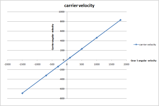
| angular velocity of gear 5 | angular velocity of the carrier |
| 100 | 46.15384615 |
| -300 | -138.4615385 |
| 500 | 230.7692308 |
| -700 | -323.0769231 |
| 1000 | 461.5384615 |
| -1500 | -692.3076923 |
| 1800 | 830.7692308 |
Graph plot obtained for the gear 5 velocities along X and carrier
velocity along Y is as follows. Please note that +ve means CW and
-ve means CCW
Add Answer to:
In the gear train shown, gears 3 and 4 are integral. Gear 3 meshes with gear...
For the gear train shown below, calculate the angular velocity of gears A and B given...
 For the gear train shown below, calculate the angular velocity of gears A and B given that NA-30, NB-20, Nc 70, D is rotating 30rpm CCW, and C is fixed. 3) (15 points)
Kinematics class 3. (25 POINTS) Planetary gear train analysis: The figure below representsa planetary gear train...
 Kinematics class
3. (25 POINTS) Planetary gear train analysis: The figure below representsa planetary gear train used in a drill head. Gear 1 rotates with the input shaft. The ring gear 3 meshes both with gear 5 and gear 6, which are the planets. Gear 2 acts as the carrier for gear 5, the output is the carrier 4 Consider the number of teeth Ni-6, N2 36, N-54, N-24 and No-9 a) Identify how many stages are needed to fully...
Kinematics class
3. (25 POINTS) Planetary gear train analysis: The figure below representsa planetary gear train used in a drill head. Gear 1 rotates with the input shaft. The ring gear 3 meshes both with gear 5 and gear 6, which are the planets. Gear 2 acts as the carrier for gear 5, the output is the carrier 4 Consider the number of teeth Ni-6, N2 36, N-54, N-24 and No-9 a) Identify how many stages are needed to fully...
Homework 6: The figure below shows a gear train where gear 1, on shaft a (input...
 Homework 6: The figure below shows a gear train where gear 1, on shaft a (input shaft), drives gear 2 with 32 teeth (denoted 32T) on shaft b, gear 3 (20T) also is on shaft b and drives gear 4 (507) on shaft c (output shaft). The pitch diameter of gears 1 and 2 are d = 24 mm and d = 48 mm. The center distance between gears 3 and 4 (distance between shafts b and c is 70mm....
In the gear train shown below, the pinion 2 is the driver, and gear 5 is...
 In the gear train shown below, the pinion 2 is the driver, and gear 5 is the output gear. All gears are spur gears has a module of 2.5mm and pressure angle of 200. The number of gear teeth are: N2 - 14, N3 - 84, N4 - 14, N5 - 70 teeth. The gear set transmits the power of 1.5KW at a constant angular velocity of XX rev/min. Where XX is the last two digits of your University ID...
Consider the following drive train. Gears are shown by their pitch diameters. Gear 2 is the...
 Consider the following drive train. Gears are shown by their pitch diameters. Gear 2 is the pinion Gear diameter not drawn to scale. N4 Ng No 12 + 3 4 6 N2 5 ng N: Question 1 100 pts All gears have a 5 mm module and 25 degree pressure angle The pinion rotates at 100 RPM and has 10 teeth Each simple gear set has a 10:1 gear ratio. Determine: Pinion pitch diameter (mm) overall train ratio [Choose ]...
3) (10 Marks) The overdrive unit shown below is sometimes used to follow a st automotive...
 3) (10 Marks) The overdrive unit shown below is sometimes used to follow a st automotive transmission to further reduce engine speed. The engine transmission) corresponds to the speed of planet carrier 3, and the drive shaft speed corresponds to that of gear 5; sun gear 2 is held stationary. speed (after the Determine the percentage reduction in engine speed obtains when the overdrive is active. Interaal gear consocted to drive shaft, 427 Stationary sun geat. 1sT Planet pinions, 127...
 For the gear train shown below, calculate the angular velocity of gears A and B given that NA-30, NB-20, Nc 70, D is rotating 30rpm CCW, and C is fixed. 3) (15 points)
 Kinematics class
3. (25 POINTS) Planetary gear train analysis: The figure below representsa planetary gear train used in a drill head. Gear 1 rotates with the input shaft. The ring gear 3 meshes both with gear 5 and gear 6, which are the planets. Gear 2 acts as the carrier for gear 5, the output is the carrier 4 Consider the number of teeth Ni-6, N2 36, N-54, N-24 and No-9 a) Identify how many stages are needed to fully...
Kinematics class
3. (25 POINTS) Planetary gear train analysis: The figure below representsa planetary gear train used in a drill head. Gear 1 rotates with the input shaft. The ring gear 3 meshes both with gear 5 and gear 6, which are the planets. Gear 2 acts as the carrier for gear 5, the output is the carrier 4 Consider the number of teeth Ni-6, N2 36, N-54, N-24 and No-9 a) Identify how many stages are needed to fully...
 Homework 6: The figure below shows a gear train where gear 1, on shaft a (input shaft), drives gear 2 with 32 teeth (denoted 32T) on shaft b, gear 3 (20T) also is on shaft b and drives gear 4 (507) on shaft c (output shaft). The pitch diameter of gears 1 and 2 are d = 24 mm and d = 48 mm. The center distance between gears 3 and 4 (distance between shafts b and c is 70mm....
 In the gear train shown below, the pinion 2 is the driver, and gear 5 is the output gear. All gears are spur gears has a module of 2.5mm and pressure angle of 200. The number of gear teeth are: N2 - 14, N3 - 84, N4 - 14, N5 - 70 teeth. The gear set transmits the power of 1.5KW at a constant angular velocity of XX rev/min. Where XX is the last two digits of your University ID...
 Consider the following drive train. Gears are shown by their pitch diameters. Gear 2 is the pinion Gear diameter not drawn to scale. N4 Ng No 12 + 3 4 6 N2 5 ng N: Question 1 100 pts All gears have a 5 mm module and 25 degree pressure angle The pinion rotates at 100 RPM and has 10 teeth Each simple gear set has a 10:1 gear ratio. Determine: Pinion pitch diameter (mm) overall train ratio [Choose ]...
 3) (10 Marks) The overdrive unit shown below is sometimes used to follow a st automotive transmission to further reduce engine speed. The engine transmission) corresponds to the speed of planet carrier 3, and the drive shaft speed corresponds to that of gear 5; sun gear 2 is held stationary. speed (after the Determine the percentage reduction in engine speed obtains when the overdrive is active. Interaal gear consocted to drive shaft, 427 Stationary sun geat. 1sT Planet pinions, 127...
Most questions answered within 3 hours.
-
How can we identify what the horizontal force is when looking at
a merry go round?...
asked 15 minutes ago -
While Dime Community Bank is based in Brooklyn; management has
decided to focus its lending activity...
asked 40 minutes ago -
1) Earnings functions, whereby the log of earnings is regressed
on years of education, years of...
asked 14 minutes ago -
Bruno Corporation is involved in the business of injection
molding of plastics. It is considering the...
asked 19 minutes ago -
What would be the vapor pressure of water at 96°C above a
solution made by dissolving...
asked 34 minutes ago -
Hydration of norbornene
Write the reaction. Discuss the intermediate. Explain how the
equilibrium in the reaction...
asked 41 minutes ago -
Suppose that a party wanted to enter an FRA that expires in 42
days and is...
asked 42 minutes ago -
ABC Ltd. estimated that a new store requires an initial
investment of $800,000. This new store...
asked 43 minutes ago -
1. Review the Nike’s marketing strategy. You must include the
company’s target market, possible market segmentation,...
asked 55 minutes ago -
One of the major advantages of ______________ is to enhance
security for private networks by keeping...
asked 1 hour ago -
Book:
Title: Framework for
Marketing Management, 15th edition
Author/s: Philip T.
Kotler, Kevin Lane Keller
1....
asked 1 hour ago -
Given Uber’s recent corporate turbulence and ongoing
initiatives, provide a holistic situational analysis of the
environment...
asked 1 hour ago