
Homework Answers
![LOOMA ellele SE MA DOMA- dt 100 mA = cavo + vo + I Svolt 0.1= c du tvo + 1 hod Taking Laplace transform 0:!,offvoce - Yocoy ]](http://img.homeworklib.com/questions/b2bbcb50-380d-11ec-84a3-5fbb1d9767bf.png?x-oss-process=image/resize,w_560)

Add Answer to:
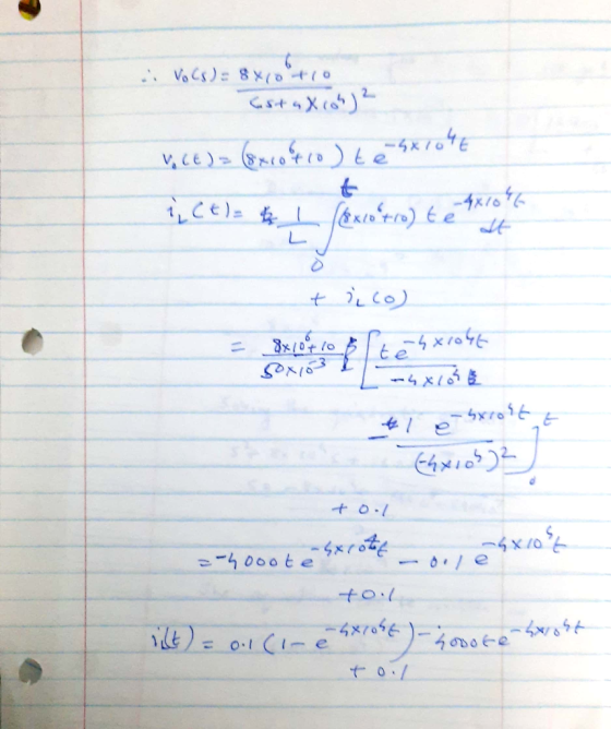
find response of the parallel RLC circuit on Figure 3. Sketch iL(t)
for tE( 0, 50us)...
1. RLC Circuits Revisited. The first example of a RLC circuit illustrates the use of circuit...
 1. RLC Circuits Revisited. The first example of a RLC circuit illustrates the use of circuit elements in the s domain to represent initial conditions and a forced response. Next an example of sinusoidal excitation will follow where the transient response and steady state response are combined into one response waveform.. Transient RLC Circuit with Initial Conditions. Consider the RLC circuit below in Figure 7.14 which has two DC sources (Vco and V) applied before and after a switch is...
Consider the series RLC circuit in Figure 1. Suppose the source voltage is initially OV, and...
 Consider the series RLC circuit in Figure 1. Suppose the source voltage is initially OV, and no energy is stored in both the capacitor and inductor. At t = 0, the source voltage is switched to 1V. Calculate the resistor, inductor and capacitor voltages, and the loop current V (t),,(t),Vc(t),i(t). Show all the steps. C1 L1 1.2u 8.2m 10 3 R1 Figure 1: A series RLC circuit
Consider the series RLC circuit in Figure 1. Suppose the source voltage is initially OV, and...
 Consider the series RLC circuit in Figure 1. Suppose the source voltage is initially OV, and no energy is stored in both the capacitor and inductor. At t = 0, the source voltage is switched to 1V. Calculate the resistor, inductor and capacitor voltages, and the loop current VROV.O.Vc),it). Show all the steps. SOL L1 n 8.2m 10 3 R1 Figure 1: A series RLC circuit
Function Generatr Inductor Model Ra R, Figure 1 Series RLC Circuit Preliminary This laboratory wi...
 Function Generatr Inductor Model Ra R, Figure 1 Series RLC Circuit Preliminary This laboratory will demonstrate how varying resistance changes the natural response of a series RLC circuit (Fig. 1). The function generator is modeled as an ideal voltage source v(t) 5 u() V in series with source resistance Rs-50Q. After measurements using an LCR meter, the inductor is modeled as an ideal L 90 mH inductor in series with resistance RL-20Q. The capacitance is C-0.22 μF. 1) Calculate the...
Section 3: Laplace transform for RLC circuit analysis (10 marks) A second-order RLC circuit with a...
 Section 3: Laplace transform for RLC circuit analysis (10 marks) A second-order RLC circuit with a dependent source is shown in Fig. 3. 22 + VO - 132 1F + 15e-2 u(t) V ) 9[1-u(t)] V Y 0.50 » Fig. 3 A second-order RLC circuit with a dependent source Take the Laplace transform of the circuit and hence find the response io(t) for t > 0. Specify whether it is an underdamped, critically damped or overdamped case. Sketch the response.
Solve it as shown but use these values instead: An RLC series circuit has a voltage...
 Solve it as shown but use these values instead: An RLC
series circuit has a voltage source given by E(t)=10 V, a
resistor of 175 Ω, an inductor of 5 H,and a capacitor of 0.01 F.
If the initial current is zero and the initial charge on the
capacitor is 8 C, determine the current in the circuit for
t>0.
An RLC series circuit has a voltage source given by E(t) = 20 V, a resistor of 140 2, an...
Solve it as shown but use these values instead: An RLC
series circuit has a voltage source given by E(t)=10 V, a
resistor of 175 Ω, an inductor of 5 H,and a capacitor of 0.01 F.
If the initial current is zero and the initial charge on the
capacitor is 8 C, determine the current in the circuit for
t>0.
An RLC series circuit has a voltage source given by E(t) = 20 V, a resistor of 140 2, an...
An RLC series circuit has a voltage source given by E(t)= 20 V, a resistor of...
 An RLC series circuit has a voltage source given by E(t)= 20 V, a resistor of 245 Q, an inductor of 7 H, and a capacitor of 0.05 F. If the initial current is zero and the initial charge on the capacitor is 9 C, determine the current in the circuit for t> 0. |(t) = (Type an exact answer, using radicals as needed.)
3. Natural response, for ? > 0 of a series R-L-C circuit has R = 1...
3. Natural response, for ? > 0 of a series R-L-C circuit has R = 1 Ω , L = 1 H and C = 1 F. The initial capacitor voltage is 4 V, and initial inductor current is zero. The series current is i. (i) Draw the time domain circuit. (ii) Draw the Laplace transform domain circuit. (iii) From (ii), determine Io =Io (s) (iv) From (iii), determine ?? = ??(?) for t > 0
Q1 a) A parallel resonant RLC circuit is driven by a current source is = 20...
 Q1 a) A parallel resonant RLC circuit is driven by a current source is = 20 cos(wt) x10-3A and shows a maximum response of 8 V at w = 1000 rad/s and 4V at w = 897.6 rad/s. Determine the value of passive components R, L and C. (15 Marks) b) The concept of resonance applies in several areas of science and Engineering. Resonance occurs in any circuit that has at least one inductor and one capacitor. Explain the condition...
(1) Consider the RC circuit shown in Figure 1. For t<0 the switch is open, and...
 (1) Consider the RC circuit shown in Figure 1. For t<0 the switch is open, and the charge stored on the capacitor is 0. At t-0 the switch is closed, and the voltage source begins charging the capacitor. Let R1-R2-220 Ω , C-0.47 μ F , Vs-5 V. (a) Write the differential equation as an expression for the capacitor voltage fort> 0 (i.e. write the differential equation) and calculate the time constant (b) Calculate the steady-state capacitor voltage R2 R1...
 1. RLC Circuits Revisited. The first example of a RLC circuit illustrates the use of circuit elements in the s domain to represent initial conditions and a forced response. Next an example of sinusoidal excitation will follow where the transient response and steady state response are combined into one response waveform.. Transient RLC Circuit with Initial Conditions. Consider the RLC circuit below in Figure 7.14 which has two DC sources (Vco and V) applied before and after a switch is...
 Consider the series RLC circuit in Figure 1. Suppose the source voltage is initially OV, and no energy is stored in both the capacitor and inductor. At t = 0, the source voltage is switched to 1V. Calculate the resistor, inductor and capacitor voltages, and the loop current V (t),,(t),Vc(t),i(t). Show all the steps. C1 L1 1.2u 8.2m 10 3 R1 Figure 1: A series RLC circuit
 Consider the series RLC circuit in Figure 1. Suppose the source voltage is initially OV, and no energy is stored in both the capacitor and inductor. At t = 0, the source voltage is switched to 1V. Calculate the resistor, inductor and capacitor voltages, and the loop current VROV.O.Vc),it). Show all the steps. SOL L1 n 8.2m 10 3 R1 Figure 1: A series RLC circuit
 Function Generatr Inductor Model Ra R, Figure 1 Series RLC Circuit Preliminary This laboratory will demonstrate how varying resistance changes the natural response of a series RLC circuit (Fig. 1). The function generator is modeled as an ideal voltage source v(t) 5 u() V in series with source resistance Rs-50Q. After measurements using an LCR meter, the inductor is modeled as an ideal L 90 mH inductor in series with resistance RL-20Q. The capacitance is C-0.22 μF. 1) Calculate the...
 Section 3: Laplace transform for RLC circuit analysis (10 marks) A second-order RLC circuit with a dependent source is shown in Fig. 3. 22 + VO - 132 1F + 15e-2 u(t) V ) 9[1-u(t)] V Y 0.50 » Fig. 3 A second-order RLC circuit with a dependent source Take the Laplace transform of the circuit and hence find the response io(t) for t > 0. Specify whether it is an underdamped, critically damped or overdamped case. Sketch the response.
 Solve it as shown but use these values instead: An RLC
series circuit has a voltage source given by E(t)=10 V, a
resistor of 175 Ω, an inductor of 5 H,and a capacitor of 0.01 F.
If the initial current is zero and the initial charge on the
capacitor is 8 C, determine the current in the circuit for
t>0.
An RLC series circuit has a voltage source given by E(t) = 20 V, a resistor of 140 2, an...
Solve it as shown but use these values instead: An RLC
series circuit has a voltage source given by E(t)=10 V, a
resistor of 175 Ω, an inductor of 5 H,and a capacitor of 0.01 F.
If the initial current is zero and the initial charge on the
capacitor is 8 C, determine the current in the circuit for
t>0.
An RLC series circuit has a voltage source given by E(t) = 20 V, a resistor of 140 2, an...
 An RLC series circuit has a voltage source given by E(t)= 20 V, a resistor of 245 Q, an inductor of 7 H, and a capacitor of 0.05 F. If the initial current is zero and the initial charge on the capacitor is 9 C, determine the current in the circuit for t> 0. |(t) = (Type an exact answer, using radicals as needed.)
 Q1 a) A parallel resonant RLC circuit is driven by a current source is = 20 cos(wt) x10-3A and shows a maximum response of 8 V at w = 1000 rad/s and 4V at w = 897.6 rad/s. Determine the value of passive components R, L and C. (15 Marks) b) The concept of resonance applies in several areas of science and Engineering. Resonance occurs in any circuit that has at least one inductor and one capacitor. Explain the condition...
 (1) Consider the RC circuit shown in Figure 1. For t<0 the switch is open, and the charge stored on the capacitor is 0. At t-0 the switch is closed, and the voltage source begins charging the capacitor. Let R1-R2-220 Ω , C-0.47 μ F , Vs-5 V. (a) Write the differential equation as an expression for the capacitor voltage fort> 0 (i.e. write the differential equation) and calculate the time constant (b) Calculate the steady-state capacitor voltage R2 R1...
Most questions answered within 3 hours.
-
Bruno Corporation is involved in the business of injection
molding of plastics. It is considering the...
asked 55 seconds from now -
What would be the vapor pressure of water at 96°C above a
solution made by dissolving...
asked 14 minutes ago -
Hydration of norbornene
Write the reaction. Discuss the intermediate. Explain how the
equilibrium in the reaction...
asked 21 minutes ago -
While Dime Community Bank is based in Brooklyn; management has
decided to focus its lending activity...
asked 20 minutes ago -
Suppose that a party wanted to enter an FRA that expires in 42
days and is...
asked 21 minutes ago -
ABC Ltd. estimated that a new store requires an initial
investment of $800,000. This new store...
asked 22 minutes ago -
1. Review the Nike’s marketing strategy. You must include the
company’s target market, possible market segmentation,...
asked 35 minutes ago -
One of the major advantages of ______________ is to enhance
security for private networks by keeping...
asked 41 minutes ago -
Book:
Title: Framework for
Marketing Management, 15th edition
Author/s: Philip T.
Kotler, Kevin Lane Keller
1....
asked 50 minutes ago -
Given Uber’s recent corporate turbulence and ongoing
initiatives, provide a holistic situational analysis of the
environment...
asked 53 minutes ago -
A sculptor has hung up a 42.0 kg horizontal rod of length 4.80 m
. One...
asked 56 minutes ago -
What is the purpose of the 2' hydroxyl group in RNA? What is
the reason this...
asked 1 hour ago