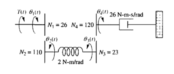
2. Perform a dynamic analysis of the physical system shown in the following illustration. Consider null initial conditions.
a) Define the equations that describe the behavior of each part
of the system, in the time domain.
b) Define the equations that describe the behavior of each part of
the system, in the frequency domain.
c) Determine the transfer function Θ4 (s) / Τ (s), considering the
indicated dynamic parameters.
Homework Answers

Add Answer to:
2. Perform a dynamic analysis of the physical system shown in
the following illustration. Consider null...
Question 3) Consider the mechanical system shown in figure, T(t) is the torque applied to shaft...
 Question 3) Consider the mechanical system shown in figure, T(t) is the torque applied to shaft 1 and z(t) is the rotation of shaft 2. J.Jz and Jz are the inertias of shafts 1,2 and 3 respectively, N,,N,N, and N, are the number of teeths of the gears,, D1, D, and D3 are the coefficient of viscous damping associated with shafts 1, 2 and 3 respectively, K is the spring constant of the torsional spring attached to shaft 3. Write...
Consider the electromechanical dynamic system shown in Figure 1(a). It consists of a cart of mass...
 This assignment is for my Engr dynamics systems class.
Consider the electromechanical dynamic system shown in Figure 1(a). It consists of a cart of mass m moving without slipping on a linear ground track. The cart is equipped with an armature-controlled DC motor, which is coupled to a rack and pinion mechanism to convert the rotational motion to translation and to create the driving force for the system. Figure 1(b) shows the simplified equivalent electric circuit and the mechanical model...
This assignment is for my Engr dynamics systems class.
Consider the electromechanical dynamic system shown in Figure 1(a). It consists of a cart of mass m moving without slipping on a linear ground track. The cart is equipped with an armature-controlled DC motor, which is coupled to a rack and pinion mechanism to convert the rotational motion to translation and to create the driving force for the system. Figure 1(b) shows the simplified equivalent electric circuit and the mechanical model...
Problem 2 (20 points total): 4 Consider the following system for Parts a-c. 2 N-s/m x2(t)...
 Problem 2 (20 points total): 4 Consider the following system for Parts a-c. 2 N-s/m x2(t) xz(t) 0000- 6 N/m 2 N-s/m xi(t) 2 N-s/m 6 N/m 4 kg 4 kg 00004 kg f(t) Frictionless Part 2a (8 points): Draw free body diagrams for each mass Part 2b (6 points): Write the equations of motion for each mass as differential equations in the time domain." Part 2c (6 points): Convert the equations of motion for each mass into algebraic equations...
Problem 2: Cart Standard Pendulum Model Consider the cart standard pendulum system shown in Figur...
 Problem 2: Cart Standard Pendulum Model Consider the cart standard pendulum system shown in Figure 1 with parameters given in Table 1 I C.8 I Ig Figure 1: Cart Standard Pendulum Schematic Syb Definition Unit Variablesr osition of the cart angle that the force applied on cart (control) mass of the cart mass ot t 123 lum makes with the vertic Parameters M5 kg utm 0.5 location of the c.g. of the pendulum above the 4 = m moment of...
For the system shown in Fig. 1, solve the following problems. (a) Find the transfer function, G(s...
 For the system shown in Fig. 1, solve the following problems. (a) Find the transfer function, G(s)X2 (s)/F(s) (b) Does the system oscillate with a unit step input (f (t))? Explain the reason (c) Decide if the system(x2 (t)) is stable with a unit step input (f (t))? Explain the reason 1. 320) 8 kg 2 N/m 4N-s/m 2N-s/m Fig. 1 2. There are two suspensions for a car as shown in Fig. 2 (a) Find the equations of each...
 Question 3) Consider the mechanical system shown in figure, T(t) is the torque applied to shaft 1 and z(t) is the rotation of shaft 2. J.Jz and Jz are the inertias of shafts 1,2 and 3 respectively, N,,N,N, and N, are the number of teeths of the gears,, D1, D, and D3 are the coefficient of viscous damping associated with shafts 1, 2 and 3 respectively, K is the spring constant of the torsional spring attached to shaft 3. Write...
 This assignment is for my Engr dynamics systems class.
Consider the electromechanical dynamic system shown in Figure 1(a). It consists of a cart of mass m moving without slipping on a linear ground track. The cart is equipped with an armature-controlled DC motor, which is coupled to a rack and pinion mechanism to convert the rotational motion to translation and to create the driving force for the system. Figure 1(b) shows the simplified equivalent electric circuit and the mechanical model...
This assignment is for my Engr dynamics systems class.
Consider the electromechanical dynamic system shown in Figure 1(a). It consists of a cart of mass m moving without slipping on a linear ground track. The cart is equipped with an armature-controlled DC motor, which is coupled to a rack and pinion mechanism to convert the rotational motion to translation and to create the driving force for the system. Figure 1(b) shows the simplified equivalent electric circuit and the mechanical model...
 Problem 2 (20 points total): 4 Consider the following system for Parts a-c. 2 N-s/m x2(t) xz(t) 0000- 6 N/m 2 N-s/m xi(t) 2 N-s/m 6 N/m 4 kg 4 kg 00004 kg f(t) Frictionless Part 2a (8 points): Draw free body diagrams for each mass Part 2b (6 points): Write the equations of motion for each mass as differential equations in the time domain." Part 2c (6 points): Convert the equations of motion for each mass into algebraic equations...
 Problem 2: Cart Standard Pendulum Model Consider the cart standard pendulum system shown in Figure 1 with parameters given in Table 1 I C.8 I Ig Figure 1: Cart Standard Pendulum Schematic Syb Definition Unit Variablesr osition of the cart angle that the force applied on cart (control) mass of the cart mass ot t 123 lum makes with the vertic Parameters M5 kg utm 0.5 location of the c.g. of the pendulum above the 4 = m moment of...
 For the system shown in Fig. 1, solve the following problems. (a) Find the transfer function, G(s)X2 (s)/F(s) (b) Does the system oscillate with a unit step input (f (t))? Explain the reason (c) Decide if the system(x2 (t)) is stable with a unit step input (f (t))? Explain the reason 1. 320) 8 kg 2 N/m 4N-s/m 2N-s/m Fig. 1 2. There are two suspensions for a car as shown in Fig. 2 (a) Find the equations of each...
Most questions answered within 3 hours.
-
Angel Corporation has $10,000,000 of
8.0% 25 year bonds dated May 1, 2018 with interest payable...
asked 22 minutes ago -
7.
________ involves individuals trading goods they already have or
providing services in exchange for something...
asked 27 minutes ago -
Share your research problem. What databases did you search as
you gathered evidence to support your...
asked 27 minutes ago -
what process occurs to form microspores and megaspores in flowering
plants?
asked 34 minutes ago -
C++
I need to use the function getData to put in all my data using
arrays....
asked 34 minutes ago -
A block is hung by a string from the inside roof of a van. When
the...
asked 40 minutes ago -
Do you think companies should not go for long term debt in their
capital structure to...
asked 49 minutes ago -
I create an address book where the user enters the name, phone
and email in the...
asked 55 minutes ago -
The production capacity for acrylonitrile
(C3H3N) in the United States exceeds 2
million pounds per year....
asked 1 hour ago -
explain and comment out your answer
43. How many address lines are required to address a...
asked 1 hour ago -
A sample of 45 observations is selected from a normal
population. The sample mean is 49,...
asked 1 hour ago -
A construction company is planning to bid on a building
contract. The bid costs the company...
asked 1 hour ago