

Homework Answers
Ans 1: Answer in the image.
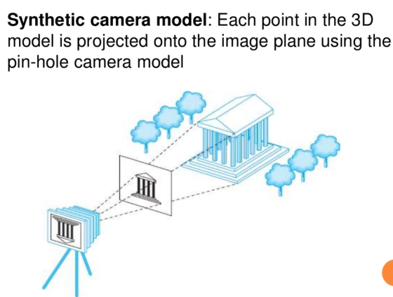
Ans 2: Synthetic Camera Model-
- In Computer Graphics, we use a synthetic camera model to mimic the behaviour of real camera.
- In this model, we avoid the inversion by placing the film plane, called the projection plane, in front of the lens.
- The clipping rectangle or clipping window determines the size of the image.
Synthetic camera model vs natural viewing system(eye)-
- Absolute versus subjective measuring of light: Simply speaking, the human eye is a subjective device. This means that your eyes work in harmony with your brain to create the images you perceive: Your eyes are adjusting the focus (by bending the light through the lens in your eyeballs) and translating photons (light) into an electrical impulse your brain can process. From there onwards, it’s all about your brain: It is continuously readjusting its colour balance according to the lighting context. In other words, our eyes know what must be seen as red or white or black etc.
- A camera, on the other hand, is an absolute measurement
device — It is measuring the light that hits a series of
sensor, but the sensor is ‘dumb’, and the signals recorded need to
be adjusted to suit the color temperature of the light illuminating
the scene, for example
-
Lens focus: In camera, the lens moves closer/further from the film to focus. In your eyes, the lens changes shape to focus: The muscles in your eyes change the actual shape of the lens inside your eyes.
-
Sensitivity to light: A film in a camera is uniformly sensitive to light. The human retina is not. Therefore, with respect to quality of image and capturing power, our eyes have a greater sensitivity in dark locations than a typical camera.
There are lighting situations that a current digital cameras cannot capture easily: The photos will come out blurry, or in a barrage of digital noise. As an example, when observing a fluorescence image of cells under a microscope, the image you can see with your eyes would be nigh-on impossible to capture for an ordinary camera. This is mainly because of the fact that the amount of light entering the camera (and your eyes) is so low.
-
Ans 3: Answer in the image.
Ans 4: Object Space or Local
space
Local space is the coordinate space that is local to your
object, i.e. where your object begins in. Imagine that you've
created your cube in a modeling software package (like Blender).
The origin of your cube is probably at (0,0,0) even
though your cube might end up at a different location in your final
application. Probably all the models you've created all have
(0,0,0) as their initial position. All the vertices of
your model are therefore in local space: they are all
local to your object.
The vertices of the container we've been using were specified as
coordinates between -0.5 and 0.5 with
0.0 as its origin. These are local coordinates.
Ans 5: World space
If we would import all our objects directly in the application
they would probably all be somewhere positioned inside each other
at the world's origin of (0,0,0) which is not what we
want. We want to define a position for each object to position them
inside a larger world. The coordinates in world space are exactly
what they sound like: the coordinates of all your vertices relative
to a (game) world. This is the coordinate space where you want your
objects transformed to in such a way that they're all scattered
around the place (preferably in a realistic fashion). The
coordinates of your object are transformed from local to world
space; this is accomplished with the model matrix.
Ans 6: Answer in image.
Ans 7: (Further adding to Ans 5)
: The model matrix is a transformation matrix that
translates, scales and/or rotates your object to place it in the
world at a location/orientation they belong to. Think of it as
transforming a house by scaling it down (it was a bit too large in
local space), translating it to a suburbia town and rotating it a
bit to the left on the y-axis so that it neatly fits with the
neighboring houses. You could think of the matrix in the previous
chapter to position the container all over the scene as a sort of
model matrix as well; we transformed the local coordinates of the
container to some different place in the scene/world.
Ans 8: Projection & it's types: It is the
process of converting a 3D object into a 2D object. It is also
defined as mapping or transformation of the object in projection
plane or view plane. The view plane is displayed surface.
(Types in the image).
Ans 9: Orthographic vs
Perspective Projection:
Orthographic projections are parallel projections. Each line that
is originally parallel will be parallel after this transformation.
The orthographic projection can be represented by a affine
transformation.
In contrast a perspective projection is not a parallel
projection and originally parallel lines will no longer be parallel
after this operation. Thus perspective projection can not be done
by a affine transform.
Ans 10: Look-At 
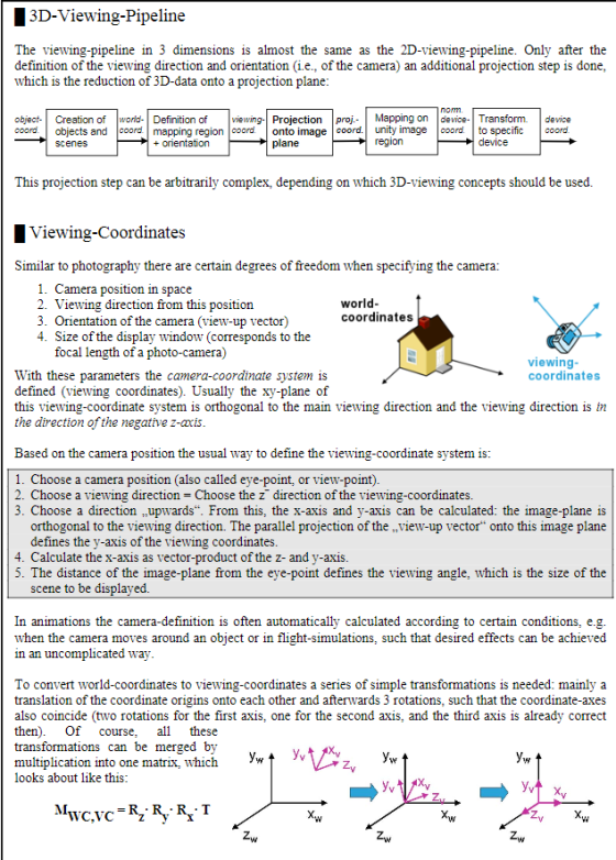

 The idea of the method is simple. In order to set a camera position
and orientation, all you really need is a point to set the camera
position in space which we will refer to as the
from point, and a point that defines what the
camera is looking at. We will refer to this point as the
to point.
The idea of the method is simple. In order to set a camera position
and orientation, all you really need is a point to set the camera
position in space which we will refer to as the
from point, and a point that defines what the
camera is looking at. We will refer to this point as the
to point.
Add Answer to:
Question 1: Illustrate the Rendering pipeline of the graphic systems. Answer: Question 2: Discuss the Synthetic...
** Please read the case study below to answer question 1, 2 and 3 Starbuck Community....
 ** Please read the case study below to answer question 1, 2 and 3 Starbuck Community. Connection. Caring. Committed. Coffee. Five Cs that describe the essence of Starbucks Corporation, what it stands for and what it wants to be as a business. With more than 19,000 stores in 62 countries, Starbucks is the world's number one specialty coffee retailer. The company also owns Seattle's Best Coffee, Tsavana. Taze, Starbucks VIA, Starbucks Refreshers, Evolution Fresh, LaBoulange, and Verismo brands. It's a...
 ** Please read the case study below to answer question 1, 2 and 3 Starbuck Community. Connection. Caring. Committed. Coffee. Five Cs that describe the essence of Starbucks Corporation, what it stands for and what it wants to be as a business. With more than 19,000 stores in 62 countries, Starbucks is the world's number one specialty coffee retailer. The company also owns Seattle's Best Coffee, Tsavana. Taze, Starbucks VIA, Starbucks Refreshers, Evolution Fresh, LaBoulange, and Verismo brands. It's a...
Most questions answered within 3 hours.
-
Executive Program Practical Connection Assignment
Subject : Operations Security.
Assignment:
Provide a reflection of at least...
asked 7 minutes ago -
Every time Casey is at bat he has a 0.4 probability of
getting on base (assume...
asked 15 minutes ago -
The Walston Company is to be liquidated and has the following
liabilities:
Income taxes
$
9,400...
asked 22 minutes ago -
If
the more comprehensive data is available in MEPS, why does the NHIS
still exist? How...
asked 43 minutes ago -
Koo argues that the Japanese economy in the 1990s suffered from
a balance sheet recession. What...
asked 36 minutes ago -
Automobile mechanics conduct diagnosis tests on 150 new cars of
particular make and model to determine...
asked 31 minutes ago -
11) Find the proceeds of a 5 year non-interest
bearing note for $6500 discounted 2.5 years...
asked 37 minutes ago -
Required: Prepare the consolidated financial statements of
Griffin Ltd at 30 June 2019.
Griffin Ltd is...
asked 46 minutes ago -
1.How large must the coefficient of static friction be between
the tires and the road if...
asked 1 hour ago -
What is the time complexity (Big-O) of the following code?
class Main
{
// Recursive...
asked 1 hour ago -
Economists look at any situation in terms of its component
parts: the people making decisions, the...
asked 1 hour ago -
What is a population?
Select one:
a. All of the individual organisms belonging to the same...
asked 1 hour ago