

Homework Answers
Add Answer to:
2.12
The forces on the gusset plate shown in the figure are F! = 6.0 kN,...
(2)A system of three forces and a couple act on a square plate ADEC as shown. 12 kN 20 kNm F 6 kN Evaluate the statical...
 (2)A system of three forces and a couple act on a square plate ADEC as shown. 12 kN 20 kNm F 6 kN Evaluate the statically equivalent system of forces F, F2 and F3 which act along the sides of the equilateral triangle ABC ( These forces are not proportional to the sides of the triangle.) 650 10 kN reaceses F F. 2 m F2 18.4 kN F1 22.48 k N F2 16.78 kN and F 3 20.7 kN F1...
The members of a truss are connected to the gusset plate. If the forces are concurrent...
 The members of a truss are connected to the gusset plate. If the forces are concurrent at point O, determine the magnitudes of F and T for equilibrium. Take θ = 90°. 9 kN
The members of a truss are connected to the gusset plate. Assuming that the forces are...
 The members of a truss are connected to the gusset plate. Assuming that the forces are concurrent at point O, determine the magnitudes of F and T for equilibrium, given that: F1 = 8 kN, F_2 = 5 kN, theta_1 = 45 degree, theta_2 = 30 degree.
The gusset plate is subjected to the forces of three members. The forces are concurrent at...
 The gusset plate is subjected to the forces of three members. The forces are concurrent at point O. Take F = 5 kN. Determine the magnitude of the tension force In member C for equilibrium. Express your answer to three significant figures and include the appropriate units. Determine the angle theta for equilibrium. Express your answer using three significant figures.
(b) A plate is subjected to multiple forces as shown in Figure Q1b. (1) Determine the...
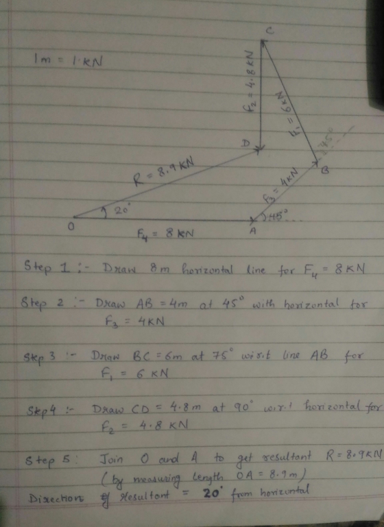
 (b) A plate is subjected to multiple forces as shown in Figure Q1b. (1) Determine the resultant force and its acting angle (ii) Draw the resultant force and its acting angle F3 = 5 kN F2 = 6 kN = 30° ♡ F. = 4kN X
40 kN 20 kN/m For the shown frame and loads, it is required to: 80 kN -Calculate reactions 6.0 m 40 kN Draw N.F.D....
 40 kN 20 kN/m For the shown frame and loads, it is required to: 80 kN -Calculate reactions 6.0 m 40 kN Draw N.F.D. S.F.D & B.M.D Figure 1 4.0 m 30m. o m 8.0 m
40 kN 20 kN/m For the shown frame and loads, it is required to: 80 kN -Calculate reactions 6.0 m 40 kN Draw N.F.D. S.F.D & B.M.D Figure 1 4.0 m 30m. o m 8.0 m
40 kN 20 kN/m For the shown frame and loads, it is required to: 80 kN -Calculate reactions 6.0 m 40 kN Draw N.F.D. S.F.D & B.M.D Figure 1 4.0 m 30m. o m 8.0 m
Consider the beam shown in (Figure 1). Suppose that F 24 kN, F2 15 kN, and...
 Consider the beam shown in (Figure 1). Suppose that F 24 kN, F2 15 kN, and F3 12 kN Follow the sign convention Part A Determine the absolute maximum bending moment in the beam due to the loading shown Express your answer to three significant figures and include the appropriate units mAxValue Figure 1 of 1> Submit Request Answer Return to Assignment Provide Feedback F3 4 m 2m o
Forces are applied to theee beams which are attached to a gusset plate of bidge. It...
 Forces are applied to theee beams which are attached to a gusset plate of bidge. It F-960 N and is along the hortzontal ats, Fo 720 N at an angle of -43 degrees from the horzontal, and F -600 N, find the horzontal and vertical components of the resutant force (FRz and Fuy, respectively), the total magnitude of the resutant force Fre and the direction of force ex measured from the hortzontal F. 4 (direction)
Determine the forces in each member of the truss shown in figure 11. Above. 120 KN...
 Determine the forces in each member of the truss shown in figure
11. Above.
120 KN 120 KN 4 m 120 KN H E F 60 KN 60 KN 4 m 40 KN 40 KN A B D 8 m +2 m|-3 m-3m|3m|3m|2m1 8 m Figure 11: A truss. GROUP 2B QUESTION 12: You have just graduated from CBU as a civil engineer. A water utility company employs you. During maintenance, in turning the water pump steadily, you exert a...
Determine the forces in each member of the truss shown in figure
11. Above.
120 KN 120 KN 4 m 120 KN H E F 60 KN 60 KN 4 m 40 KN 40 KN A B D 8 m +2 m|-3 m-3m|3m|3m|2m1 8 m Figure 11: A truss. GROUP 2B QUESTION 12: You have just graduated from CBU as a civil engineer. A water utility company employs you. During maintenance, in turning the water pump steadily, you exert a...
Uetii2015Marks) (CLOI : 100%) The eye-bot " shown in the figure is subjected to forces F30 KN, an...
 uetii2015Marks) (CLOI : 100%) The eye-bot " shown in the figure is subjected to forces F30 KN, and F2 -50 KN. Determine: a) The magnitude of the resultant of forces Fi and F2 b) The angles that the resultant make with x, y, and z axes B Sn 2 m c)The moment vector produced by forces F, and F, about c line AB
uetii2015Marks) (CLOI : 100%) The eye-bot " shown in the figure is subjected to forces F30 KN,...
uetii2015Marks) (CLOI : 100%) The eye-bot " shown in the figure is subjected to forces F30 KN, and F2 -50 KN. Determine: a) The magnitude of the resultant of forces Fi and F2 b) The angles that the resultant make with x, y, and z axes B Sn 2 m c)The moment vector produced by forces F, and F, about c line AB
uetii2015Marks) (CLOI : 100%) The eye-bot " shown in the figure is subjected to forces F30 KN,...
 (2)A system of three forces and a couple act on a square plate ADEC as shown. 12 kN 20 kNm F 6 kN Evaluate the statically equivalent system of forces F, F2 and F3 which act along the sides of the equilateral triangle ABC ( These forces are not proportional to the sides of the triangle.) 650 10 kN reaceses F F. 2 m F2 18.4 kN F1 22.48 k N F2 16.78 kN and F 3 20.7 kN F1...
 The members of a truss are connected to the gusset plate. If the forces are concurrent at point O, determine the magnitudes of F and T for equilibrium. Take θ = 90°. 9 kN
 The members of a truss are connected to the gusset plate. Assuming that the forces are concurrent at point O, determine the magnitudes of F and T for equilibrium, given that: F1 = 8 kN, F_2 = 5 kN, theta_1 = 45 degree, theta_2 = 30 degree.
 The gusset plate is subjected to the forces of three members. The forces are concurrent at point O. Take F = 5 kN. Determine the magnitude of the tension force In member C for equilibrium. Express your answer to three significant figures and include the appropriate units. Determine the angle theta for equilibrium. Express your answer using three significant figures.
 (b) A plate is subjected to multiple forces as shown in Figure Q1b. (1) Determine the resultant force and its acting angle (ii) Draw the resultant force and its acting angle F3 = 5 kN F2 = 6 kN = 30° ♡ F. = 4kN X
 40 kN 20 kN/m For the shown frame and loads, it is required to: 80 kN -Calculate reactions 6.0 m 40 kN Draw N.F.D. S.F.D & B.M.D Figure 1 4.0 m 30m. o m 8.0 m
40 kN 20 kN/m For the shown frame and loads, it is required to: 80 kN -Calculate reactions 6.0 m 40 kN Draw N.F.D. S.F.D & B.M.D Figure 1 4.0 m 30m. o m 8.0 m
40 kN 20 kN/m For the shown frame and loads, it is required to: 80 kN -Calculate reactions 6.0 m 40 kN Draw N.F.D. S.F.D & B.M.D Figure 1 4.0 m 30m. o m 8.0 m
 Consider the beam shown in (Figure 1). Suppose that F 24 kN, F2 15 kN, and F3 12 kN Follow the sign convention Part A Determine the absolute maximum bending moment in the beam due to the loading shown Express your answer to three significant figures and include the appropriate units mAxValue Figure 1 of 1> Submit Request Answer Return to Assignment Provide Feedback F3 4 m 2m o
 Forces are applied to theee beams which are attached to a gusset plate of bidge. It F-960 N and is along the hortzontal ats, Fo 720 N at an angle of -43 degrees from the horzontal, and F -600 N, find the horzontal and vertical components of the resutant force (FRz and Fuy, respectively), the total magnitude of the resutant force Fre and the direction of force ex measured from the hortzontal F. 4 (direction)
 Determine the forces in each member of the truss shown in figure
11. Above.
120 KN 120 KN 4 m 120 KN H E F 60 KN 60 KN 4 m 40 KN 40 KN A B D 8 m +2 m|-3 m-3m|3m|3m|2m1 8 m Figure 11: A truss. GROUP 2B QUESTION 12: You have just graduated from CBU as a civil engineer. A water utility company employs you. During maintenance, in turning the water pump steadily, you exert a...
Determine the forces in each member of the truss shown in figure
11. Above.
120 KN 120 KN 4 m 120 KN H E F 60 KN 60 KN 4 m 40 KN 40 KN A B D 8 m +2 m|-3 m-3m|3m|3m|2m1 8 m Figure 11: A truss. GROUP 2B QUESTION 12: You have just graduated from CBU as a civil engineer. A water utility company employs you. During maintenance, in turning the water pump steadily, you exert a...
 uetii2015Marks) (CLOI : 100%) The eye-bot " shown in the figure is subjected to forces F30 KN, and F2 -50 KN. Determine: a) The magnitude of the resultant of forces Fi and F2 b) The angles that the resultant make with x, y, and z axes B Sn 2 m c)The moment vector produced by forces F, and F, about c line AB
uetii2015Marks) (CLOI : 100%) The eye-bot " shown in the figure is subjected to forces F30 KN,...
uetii2015Marks) (CLOI : 100%) The eye-bot " shown in the figure is subjected to forces F30 KN, and F2 -50 KN. Determine: a) The magnitude of the resultant of forces Fi and F2 b) The angles that the resultant make with x, y, and z axes B Sn 2 m c)The moment vector produced by forces F, and F, about c line AB
uetii2015Marks) (CLOI : 100%) The eye-bot " shown in the figure is subjected to forces F30 KN,...
Most questions answered within 3 hours.
-
Accent Software faces the following conditions. All of these
support Accent’s use of a market-penetration pricing...
asked 14 minutes ago -
A mathematically inclined friend emails you the following
instructions: "Meet me in the cafeteria the first...
asked 16 minutes ago -
A monopoly sells in two countries . The demand curves in the two
countries are p1...
asked 1 hour ago -
A .15kg rubber ball is bounced off a wall. Before hitting the
wall, the ball moves...
asked 1 hour ago -
A manufacturing company preparing to build a new plant is
considering three potential locations for it....
asked 1 hour ago -
B. If compound Y has approximately the same values of solubility
in toluene as compound X,...
asked 2 hours ago -
Oscar Inc. has inventory in Japan valued at 39,051,000 Yen one
year ago. One year ago...
asked 2 hours ago -
If Canada suffered from "fundamental disequilibrium," and its
government choose not to devalue its currency, a...
asked 2 hours ago -
4. How many input & output Key Value Pairs are passed into,
and emitted out of...
asked 2 hours ago -
Why would your heart not function well if constructed of
skeletal muscle? What is the particular...
asked 3 hours ago -
Please respond to this essay question in full essay form for
Chemistry 1102 Organic and Biochemistry:...
asked 3 hours ago -
Determine the head loss and velocity of flow in a water supply main
of 15.0 cm...
asked 3 hours ago