
Homework Answers


Add Answer to:
An input signal oscillates sinusoidally between 15 and 45 V with a frequency of 100 Hz....
5) An input signal oscillates sinusoidally between 12 and 24 V with a frequency of 120...
5) An input signal oscillates sinusoidally between 12 and 24 V with a frequency of 120 Hz. It is measured with an instrument with damping ratio of 0.5 and ringing frequency of 1000 Hz. Determine the transmission, resonance, and filter band in hertz. Do the same for a damping ratio of 0.707.
Consider a message signal m(t) that contains frequency components at 100, 200, and 400 Hz. This...
 Consider a message signal m(t) that contains frequency components at 100, 200, and 400 Hz. This signal is used to modulate a carrier at 100 kHz to obtain an SSB modulated signal. At the receiver, in the coherent detector is used to recover m(t), the oscillator supplies a sine wave of frequency 100.02 kHz instead of a cosine wave of frequency 100 kHz. (a) Determine the frequency components of the detector output if the SSB signal transmits the upper sideband....
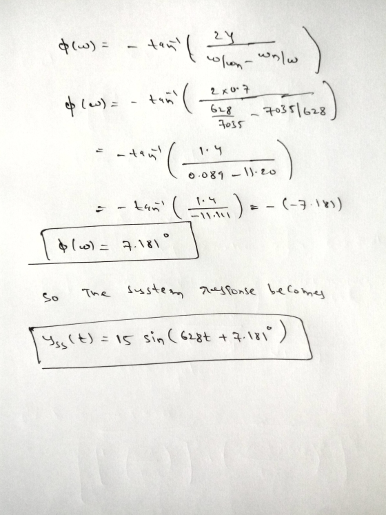
We have a filter and the bode diagram is shown as below figure. The input signal...
 We have a filter and the bode diagram is shown as below
figure.
The input signal is shown as below figure, What will be the
output signal in steady state?
Bode Diagram 0 -10 Magnitude (dB) -20 -30 -48 Phase (deg) 45 -90 10-2 10-1 100 101 102 Frequency (Hz) - Input 0.5 MT Voltage(V) -0.5 0.05 0.1 0.15 0.2 0.3 0.35 0.4 0.45 0.5 0.25 Time(s) Input Output 0.5 0 -0.5 -1 9.5 9.55 9.6 9.65 9.7 9.8 9.85...
We have a filter and the bode diagram is shown as below
figure.
The input signal is shown as below figure, What will be the
output signal in steady state?
Bode Diagram 0 -10 Magnitude (dB) -20 -30 -48 Phase (deg) 45 -90 10-2 10-1 100 101 102 Frequency (Hz) - Input 0.5 MT Voltage(V) -0.5 0.05 0.1 0.15 0.2 0.3 0.35 0.4 0.45 0.5 0.25 Time(s) Input Output 0.5 0 -0.5 -1 9.5 9.55 9.6 9.65 9.7 9.8 9.85...
Problem 1 A sinusodial signal x(t)- sin2t (t in seconds) is input to a system with frequency resp...
 Problem 1 A sinusodial signal x(t)- sin2t (t in seconds) is input to a system with frequency response: H(G What signal y(t) is observed at the output? Problem 2 The inverse Fourier transform of a system frequency response is given by h(t)t. The signal x(t) 3 cos(4t 0.5) is input to the system (t in seconds). (a) What is the expression of the signal y(t) at the system output? (b) What is the power attenuation in dB caused by the...
Measurements #6. The relation between input Ti and output X of a liquid bulb thermometer is...
 Measurements
#6. The relation between input Ti and output X of a liquid bulb thermometer is given by: dx 23.0dt + 2.0-2.0 Ti measured in mm and Ti is the input measured in is 0 mm. The meter is under a step input from 0 oC (at 0) to 90 oC (t> 0). Find the reading of the where X is output oC. Find time constant and static sensitivity of the instrument (3 +2 pts). At 0 oC the X...
Measurements
#6. The relation between input Ti and output X of a liquid bulb thermometer is given by: dx 23.0dt + 2.0-2.0 Ti measured in mm and Ti is the input measured in is 0 mm. The meter is under a step input from 0 oC (at 0) to 90 oC (t> 0). Find the reading of the where X is output oC. Find time constant and static sensitivity of the instrument (3 +2 pts). At 0 oC the X...
Problem 3) (15 points) An RC filter is designed with a cutoff frequency of 100 Hz. If a low-pass first order filter is used, determine the attenuation (Attenuation %, and Attenuation(dB)) of the f...
 Problem 3) (15 points) An RC filter is designed with a cutoff frequency of 100 Hz. If a low-pass first order filter is used, determine the attenuation (Attenuation %, and Attenuation(dB)) of the filtered analog signal at 50, 75 and 200 Hz. (use k -1) o Determine the order of the filter if magnitude ratio of <0.01 is needed at 200 Hz.
Problem 3) (15 points) An RC filter is designed with a cutoff frequency of 100 Hz. If a...
Problem 3) (15 points) An RC filter is designed with a cutoff frequency of 100 Hz. If a low-pass first order filter is used, determine the attenuation (Attenuation %, and Attenuation(dB)) of the filtered analog signal at 50, 75 and 200 Hz. (use k -1) o Determine the order of the filter if magnitude ratio of <0.01 is needed at 200 Hz.
Problem 3) (15 points) An RC filter is designed with a cutoff frequency of 100 Hz. If a...
The input sinusoid has a 1 V amplitude and 5,000 Hz frequency. Analyze the circuit of...
 The input sinusoid has a 1 V amplitude and 5,000 Hz
frequency.
Analyze the circuit of Figure to determine, for each value of R_L. Use the given values and answer questions a-g. Please show work. V. Load Figure 2 Using Figure 2 Calculate for the questions a-g using the values given of R_T. RLand inductor resistance values for the parameters in the circuit of Figure 2.ee . 1.00-12.000 es the input sinusold her a IV.,amplitude and a Se frequency) ....
The input sinusoid has a 1 V amplitude and 5,000 Hz
frequency.
Analyze the circuit of Figure to determine, for each value of R_L. Use the given values and answer questions a-g. Please show work. V. Load Figure 2 Using Figure 2 Calculate for the questions a-g using the values given of R_T. RLand inductor resistance values for the parameters in the circuit of Figure 2.ee . 1.00-12.000 es the input sinusold her a IV.,amplitude and a Se frequency) ....
Change the frequency to 50kHz. Only do the first part to find the -45° shift. What...
 Change the frequency to 50kHz. Only do the first part to find
the -45° shift. What is the value of I that results in a -45° phase
shift?
Choose correct answer from the following:
a. 69.68E-6
b. 771.88E-6
c. 74.03E-6
d. 76.25E-6
e. 78.54E-6
f. 80.90E-6
g. 83.32E-6
h. 85.82E-6
SIM *4.53 In the circuit shown in Fig. P4.53, is a de current and v, is a sinusoidal signal with small amplitude (less than 10 mV) and a frequency of...
Change the frequency to 50kHz. Only do the first part to find
the -45° shift. What is the value of I that results in a -45° phase
shift?
Choose correct answer from the following:
a. 69.68E-6
b. 771.88E-6
c. 74.03E-6
d. 76.25E-6
e. 78.54E-6
f. 80.90E-6
g. 83.32E-6
h. 85.82E-6
SIM *4.53 In the circuit shown in Fig. P4.53, is a de current and v, is a sinusoidal signal with small amplitude (less than 10 mV) and a frequency of...
(14%) 6. Consider an FM modulator with output )-100 cos(2(1000)r+(0) The modulator operates with fa = 8 and has the input message signal The modulator is followed by a bandpass filter with a...
 (14%) 6. Consider an FM modulator with output )-100 cos(2(1000)r+(0) The modulator operates with fa = 8 and has the input message signal The modulator is followed by a bandpass filter with a a bandwidth of 56HZ, as shown in the following figure. Determine the power ratio and the power at the fiter oput center frequency of 1000HZ and Bandpass filter PM Output Center 1000 Hz Bandwidth 56 Hz mt-5 cos 2(8)r modulator -1000 Hz (a) FM system 39.1 39.1365...
u must show an expression (equation) before inserting in the numbers" β-40. The input signal results in a base 1. For the class A amplifier circuit of fig. Pl, current having a peak valu...
 u must show an expression (equation) before inserting in the numbers" β-40. The input signal results in a base 1. For the class A amplifier circuit of fig. Pl, current having a peak value of 5 mA. Determine: (a) The input power (P(d) and output power (Pofac). (b) The power loss (Ploss) and the efficiency (7) of this amplifier. 15 Vcc (18 V) Re-16 Ω 1.2 k2 Ci 100 pF Fig. PI
u must show an expression (equation) before inserting...
u must show an expression (equation) before inserting in the numbers" β-40. The input signal results in a base 1. For the class A amplifier circuit of fig. Pl, current having a peak value of 5 mA. Determine: (a) The input power (P(d) and output power (Pofac). (b) The power loss (Ploss) and the efficiency (7) of this amplifier. 15 Vcc (18 V) Re-16 Ω 1.2 k2 Ci 100 pF Fig. PI
u must show an expression (equation) before inserting...
 Consider a message signal m(t) that contains frequency components at 100, 200, and 400 Hz. This signal is used to modulate a carrier at 100 kHz to obtain an SSB modulated signal. At the receiver, in the coherent detector is used to recover m(t), the oscillator supplies a sine wave of frequency 100.02 kHz instead of a cosine wave of frequency 100 kHz. (a) Determine the frequency components of the detector output if the SSB signal transmits the upper sideband....
 We have a filter and the bode diagram is shown as below
figure.
The input signal is shown as below figure, What will be the
output signal in steady state?
Bode Diagram 0 -10 Magnitude (dB) -20 -30 -48 Phase (deg) 45 -90 10-2 10-1 100 101 102 Frequency (Hz) - Input 0.5 MT Voltage(V) -0.5 0.05 0.1 0.15 0.2 0.3 0.35 0.4 0.45 0.5 0.25 Time(s) Input Output 0.5 0 -0.5 -1 9.5 9.55 9.6 9.65 9.7 9.8 9.85...
We have a filter and the bode diagram is shown as below
figure.
The input signal is shown as below figure, What will be the
output signal in steady state?
Bode Diagram 0 -10 Magnitude (dB) -20 -30 -48 Phase (deg) 45 -90 10-2 10-1 100 101 102 Frequency (Hz) - Input 0.5 MT Voltage(V) -0.5 0.05 0.1 0.15 0.2 0.3 0.35 0.4 0.45 0.5 0.25 Time(s) Input Output 0.5 0 -0.5 -1 9.5 9.55 9.6 9.65 9.7 9.8 9.85...
 Problem 1 A sinusodial signal x(t)- sin2t (t in seconds) is input to a system with frequency response: H(G What signal y(t) is observed at the output? Problem 2 The inverse Fourier transform of a system frequency response is given by h(t)t. The signal x(t) 3 cos(4t 0.5) is input to the system (t in seconds). (a) What is the expression of the signal y(t) at the system output? (b) What is the power attenuation in dB caused by the...
 Measurements
#6. The relation between input Ti and output X of a liquid bulb thermometer is given by: dx 23.0dt + 2.0-2.0 Ti measured in mm and Ti is the input measured in is 0 mm. The meter is under a step input from 0 oC (at 0) to 90 oC (t> 0). Find the reading of the where X is output oC. Find time constant and static sensitivity of the instrument (3 +2 pts). At 0 oC the X...
Measurements
#6. The relation between input Ti and output X of a liquid bulb thermometer is given by: dx 23.0dt + 2.0-2.0 Ti measured in mm and Ti is the input measured in is 0 mm. The meter is under a step input from 0 oC (at 0) to 90 oC (t> 0). Find the reading of the where X is output oC. Find time constant and static sensitivity of the instrument (3 +2 pts). At 0 oC the X...
 Problem 3) (15 points) An RC filter is designed with a cutoff frequency of 100 Hz. If a low-pass first order filter is used, determine the attenuation (Attenuation %, and Attenuation(dB)) of the filtered analog signal at 50, 75 and 200 Hz. (use k -1) o Determine the order of the filter if magnitude ratio of <0.01 is needed at 200 Hz.
Problem 3) (15 points) An RC filter is designed with a cutoff frequency of 100 Hz. If a...
Problem 3) (15 points) An RC filter is designed with a cutoff frequency of 100 Hz. If a low-pass first order filter is used, determine the attenuation (Attenuation %, and Attenuation(dB)) of the filtered analog signal at 50, 75 and 200 Hz. (use k -1) o Determine the order of the filter if magnitude ratio of <0.01 is needed at 200 Hz.
Problem 3) (15 points) An RC filter is designed with a cutoff frequency of 100 Hz. If a...
 The input sinusoid has a 1 V amplitude and 5,000 Hz
frequency.
Analyze the circuit of Figure to determine, for each value of R_L. Use the given values and answer questions a-g. Please show work. V. Load Figure 2 Using Figure 2 Calculate for the questions a-g using the values given of R_T. RLand inductor resistance values for the parameters in the circuit of Figure 2.ee . 1.00-12.000 es the input sinusold her a IV.,amplitude and a Se frequency) ....
The input sinusoid has a 1 V amplitude and 5,000 Hz
frequency.
Analyze the circuit of Figure to determine, for each value of R_L. Use the given values and answer questions a-g. Please show work. V. Load Figure 2 Using Figure 2 Calculate for the questions a-g using the values given of R_T. RLand inductor resistance values for the parameters in the circuit of Figure 2.ee . 1.00-12.000 es the input sinusold her a IV.,amplitude and a Se frequency) ....
 Change the frequency to 50kHz. Only do the first part to find
the -45° shift. What is the value of I that results in a -45° phase
shift?
Choose correct answer from the following:
a. 69.68E-6
b. 771.88E-6
c. 74.03E-6
d. 76.25E-6
e. 78.54E-6
f. 80.90E-6
g. 83.32E-6
h. 85.82E-6
SIM *4.53 In the circuit shown in Fig. P4.53, is a de current and v, is a sinusoidal signal with small amplitude (less than 10 mV) and a frequency of...
Change the frequency to 50kHz. Only do the first part to find
the -45° shift. What is the value of I that results in a -45° phase
shift?
Choose correct answer from the following:
a. 69.68E-6
b. 771.88E-6
c. 74.03E-6
d. 76.25E-6
e. 78.54E-6
f. 80.90E-6
g. 83.32E-6
h. 85.82E-6
SIM *4.53 In the circuit shown in Fig. P4.53, is a de current and v, is a sinusoidal signal with small amplitude (less than 10 mV) and a frequency of...
 (14%) 6. Consider an FM modulator with output )-100 cos(2(1000)r+(0) The modulator operates with fa = 8 and has the input message signal The modulator is followed by a bandpass filter with a a bandwidth of 56HZ, as shown in the following figure. Determine the power ratio and the power at the fiter oput center frequency of 1000HZ and Bandpass filter PM Output Center 1000 Hz Bandwidth 56 Hz mt-5 cos 2(8)r modulator -1000 Hz (a) FM system 39.1 39.1365...
 u must show an expression (equation) before inserting in the numbers" β-40. The input signal results in a base 1. For the class A amplifier circuit of fig. Pl, current having a peak value of 5 mA. Determine: (a) The input power (P(d) and output power (Pofac). (b) The power loss (Ploss) and the efficiency (7) of this amplifier. 15 Vcc (18 V) Re-16 Ω 1.2 k2 Ci 100 pF Fig. PI
u must show an expression (equation) before inserting...
u must show an expression (equation) before inserting in the numbers" β-40. The input signal results in a base 1. For the class A amplifier circuit of fig. Pl, current having a peak value of 5 mA. Determine: (a) The input power (P(d) and output power (Pofac). (b) The power loss (Ploss) and the efficiency (7) of this amplifier. 15 Vcc (18 V) Re-16 Ω 1.2 k2 Ci 100 pF Fig. PI
u must show an expression (equation) before inserting...
Most questions answered within 3 hours.
-
Do not neglect the old for the new. The existing business must
not lose priority simply...
asked 15 minutes ago -
Kylie is a single mom with two dependent children,
Tanner, age 7 and Olivia, age 11....
asked 1 hour ago -
Phosphorous + bromine = phosphorous tribromide. If 35.0 g of
bromine are reacted and 27.9 grams...
asked 3 hours ago -
Derive the long wavelength limit of the Planck energy density
distribution
asked 2 hours ago -
Calculate the pH of each of the following solutions.
0.50 M HBr
3.1×10⁻⁴ M KOH
4.2×10⁻⁵...
asked 6 hours ago -
For the year ended December 31, Depot Max’s cost of merchandise
sold was $85,600. Inventory at the...
asked 6 hours ago -
Week 10 - Professional Memo Assignment
Professional Memo Assignment
Your mission for this week, should you...
asked 6 hours ago -
Write a Python program that stores the data for each
player on the team, and it...
asked 6 hours ago -
In
the last 3 months, mike never knows when he is going to get his
allowance...
asked 7 hours ago -
Is Ca(OH)2 a Bronsted base, Lewis base, or both? Why?
asked 6 hours ago -
1A- Why don’t voters complain about U.S. tariffs on imported
sugar?
Because sugar is only a...
asked 7 hours ago -
Cash Payback Period
Primera Banco is evaluating two capital investment proposals for
a drive-up ATM kiosk,...
asked 7 hours ago