5) An input signal oscillates sinusoidally between 12 and 24 V with a frequency of 120...
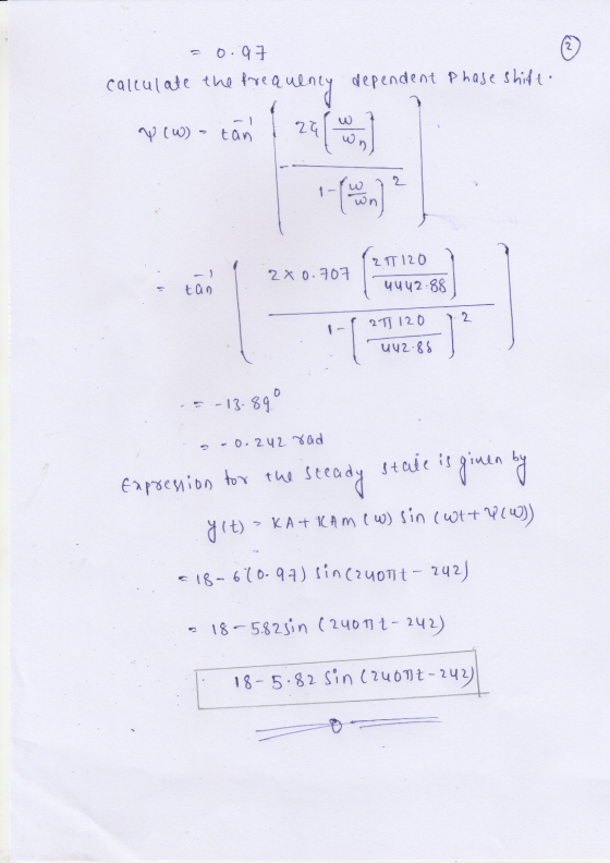
5) An input signal oscillates sinusoidally between 12 and 24 V with a frequency of 120 Hz. It is measured with an instrument with damping ratio of 0.5 and ringing frequency of 1000 Hz. Determine the transmission, resonance, and filter band in hertz. Do the same for a damping ratio of 0.707.
Homework Answers
ANSWER:-
Given that
An input signal oscillates sinusoidally between 12 and 24 V
with a frequency of 120 Hz
with damping ratio of 0.5
and ringing frequency of 1000 Hz
a damping ratio of 0.707.

Add Answer to:
5) An input signal oscillates sinusoidally between 12 and 24 V
with a frequency of 120...
An input signal oscillates sinusoidally between 15 and 45 V with a frequency of 100 Hz....
 An input signal oscillates sinusoidally between 15 and 45 V with a frequency of 100 Hz. It is measured with an instrument having a damping ratio of 0.7, ringing frequency of 800 Hz, static sensitivity of 0.5 V/. Determine the output signal function.
Problem 1 A sinusodial signal x(t)- sin2t (t in seconds) is input to a system with frequency resp...
 Problem 1 A sinusodial signal x(t)- sin2t (t in seconds) is input to a system with frequency response: H(G What signal y(t) is observed at the output? Problem 2 The inverse Fourier transform of a system frequency response is given by h(t)t. The signal x(t) 3 cos(4t 0.5) is input to the system (t in seconds). (a) What is the expression of the signal y(t) at the system output? (b) What is the power attenuation in dB caused by the...
5) Consider the following second-order bandpass filter. As input voltage, apply V(t) 100Ω, C-4.7 μF. and L-10mH. sin(wt).R in Vout Fig 9: Second-order band-pass filter a) Determine the frequenc...
 5) Consider the following second-order bandpass filter. As input voltage, apply V(t) 100Ω, C-4.7 μF. and L-10mH. sin(wt).R in Vout Fig 9: Second-order band-pass filter a) Determine the frequency response function H(ju) Ve-ju) / Vm(ju) and sketch the magnitude and phase characteristics versus w by calaulation. Calculate the theoretical cutoff frequency of the filter Using PSpice AC analysis, plot magnitude lHju)l and phase ф characteristics of the filter, between 1 Hz-100 KHz b) c)
5) Consider the following second-order bandpass...
5) Consider the following second-order bandpass filter. As input voltage, apply V(t) 100Ω, C-4.7 μF. and L-10mH. sin(wt).R in Vout Fig 9: Second-order band-pass filter a) Determine the frequency response function H(ju) Ve-ju) / Vm(ju) and sketch the magnitude and phase characteristics versus w by calaulation. Calculate the theoretical cutoff frequency of the filter Using PSpice AC analysis, plot magnitude lHju)l and phase ф characteristics of the filter, between 1 Hz-100 KHz b) c)
5) Consider the following second-order bandpass...
PROBLEMS Given in5 cos (400 120%) A, determine the period of he current and the frequency...
 PROBLEMS Given in5 cos (400 120%) A, determine the period of he current and the frequency in Hertz. s galculate the current in the resistor in Fig. P8.S if the voltage input is (a) (0)-10 cos (3771 +180°%) V (b) 00 12 sin (377t +45) V Give the answers in both the time and frequency domains 8.2/Determine the relative phase relationship of the two waves ana M(010 cos (377t- 30) v n)10 cos (3771 +90*) v e.9) Given the following...
Determine the period number of the ufk-4 cos(K+TT/2) discrete time signal! Select one: O A. 34 O ...
 Determine the period number of the ufk-4 cos(K+TT/2) discrete time signal! Select one: O A. 34 O D. Non periodic O E. 34/3 A coil (L 5 mH) is parallel connected to two serially connected resistors (6 kΩ and 4 k2). Calculate the time constant of the above two-pole! Select one: Ο Α.0.5s OC. 5 s Ο D. 0.5 με Ο Ε.0.5 Ms Consider the following sequential network: Z2 Di Ct ㄍ洼 S2 Q2 CLK Choose which function does this...
4 & 5 please thumbs up kW 60 Hz 24 Hz frequency converter 12 7 kW...
 4
& 5 please thumbs up
kW 60 Hz 24 Hz frequency converter 12 7 kW kW P P 3 kW rotor Par kW stator 120 11 (1- kw 9.55 P Tm [MF1 Figure 2 Power distribution for the wind turbine 4. MF2) A 93 % -efficient 100-hp motor runs 6,000 hours per year and produces power for a fan that requires 75 hp of shaft work. ($0.1/kWh flat rate) Calculate the annual operating cost of the motor if the...
4
& 5 please thumbs up
kW 60 Hz 24 Hz frequency converter 12 7 kW kW P P 3 kW rotor Par kW stator 120 11 (1- kw 9.55 P Tm [MF1 Figure 2 Power distribution for the wind turbine 4. MF2) A 93 % -efficient 100-hp motor runs 6,000 hours per year and produces power for a fan that requires 75 hp of shaft work. ($0.1/kWh flat rate) Calculate the annual operating cost of the motor if the...
please write code in MATLAB as well 5. (12 points) Create the following signal in Matlab:...
 please write code in MATLAB as well
5. (12 points) Create the following signal in Matlab: x[n] = u(n) - u[n-6] a. Mathematically compute yi[n] = x[n] * x[n] where * means convolution. Now use the conv command to perform the convolution. Graph x[n) and the resulting y(n), both over the interval Osns 20. How many non-zero terms does y(n) have? Does your computational result agree with the Matlab result? b. Repeat a. but this time with yz[n] = x[n]*h[n)...
please write code in MATLAB as well
5. (12 points) Create the following signal in Matlab: x[n] = u(n) - u[n-6] a. Mathematically compute yi[n] = x[n] * x[n] where * means convolution. Now use the conv command to perform the convolution. Graph x[n) and the resulting y(n), both over the interval Osns 20. How many non-zero terms does y(n) have? Does your computational result agree with the Matlab result? b. Repeat a. but this time with yz[n] = x[n]*h[n)...
I am currently trying to figure out the experiment below. Please complete Table 1 with an...
 I am currently trying to figure out the experiment below. Please
complete Table 1 with an explanation, I appreciate it thank
you! Promise to give thumbs up!
Introduction The phase differences between the output voltage, the voltage across the inductor, the voltage across the capacitor, and the voltage across the resistor will be examined at resonant frequency. The voltage and phase relationship will also be examined for frequencies above and below resonance. Theory An inductor, a capacitor, and a resistor are...
I am currently trying to figure out the experiment below. Please
complete Table 1 with an explanation, I appreciate it thank
you! Promise to give thumbs up!
Introduction The phase differences between the output voltage, the voltage across the inductor, the voltage across the capacitor, and the voltage across the resistor will be examined at resonant frequency. The voltage and phase relationship will also be examined for frequencies above and below resonance. Theory An inductor, a capacitor, and a resistor are...
Please help with question 2,3 and 4 and filling out the table Lab 12. Sound Waves...
 Please help with question 2,3
and 4 and filling out the table
Lab 12. Sound Waves and Beats Introduction Sound waves consist of a series of air pressure variations. A Microphone diaphragm records these variations by moving in response to the pressure changes. The diaphragm motion is then converted to an electrical signal. Using a Microphone and an interface, you can explore the properties of common sounds. The first property you will measure is the period, or the time for...
Please help with question 2,3
and 4 and filling out the table
Lab 12. Sound Waves and Beats Introduction Sound waves consist of a series of air pressure variations. A Microphone diaphragm records these variations by moving in response to the pressure changes. The diaphragm motion is then converted to an electrical signal. Using a Microphone and an interface, you can explore the properties of common sounds. The first property you will measure is the period, or the time for...
 An input signal oscillates sinusoidally between 15 and 45 V with a frequency of 100 Hz. It is measured with an instrument having a damping ratio of 0.7, ringing frequency of 800 Hz, static sensitivity of 0.5 V/. Determine the output signal function.
 Problem 1 A sinusodial signal x(t)- sin2t (t in seconds) is input to a system with frequency response: H(G What signal y(t) is observed at the output? Problem 2 The inverse Fourier transform of a system frequency response is given by h(t)t. The signal x(t) 3 cos(4t 0.5) is input to the system (t in seconds). (a) What is the expression of the signal y(t) at the system output? (b) What is the power attenuation in dB caused by the...
 5) Consider the following second-order bandpass filter. As input voltage, apply V(t) 100Ω, C-4.7 μF. and L-10mH. sin(wt).R in Vout Fig 9: Second-order band-pass filter a) Determine the frequency response function H(ju) Ve-ju) / Vm(ju) and sketch the magnitude and phase characteristics versus w by calaulation. Calculate the theoretical cutoff frequency of the filter Using PSpice AC analysis, plot magnitude lHju)l and phase ф characteristics of the filter, between 1 Hz-100 KHz b) c)
5) Consider the following second-order bandpass...
5) Consider the following second-order bandpass filter. As input voltage, apply V(t) 100Ω, C-4.7 μF. and L-10mH. sin(wt).R in Vout Fig 9: Second-order band-pass filter a) Determine the frequency response function H(ju) Ve-ju) / Vm(ju) and sketch the magnitude and phase characteristics versus w by calaulation. Calculate the theoretical cutoff frequency of the filter Using PSpice AC analysis, plot magnitude lHju)l and phase ф characteristics of the filter, between 1 Hz-100 KHz b) c)
5) Consider the following second-order bandpass...
 PROBLEMS Given in5 cos (400 120%) A, determine the period of he current and the frequency in Hertz. s galculate the current in the resistor in Fig. P8.S if the voltage input is (a) (0)-10 cos (3771 +180°%) V (b) 00 12 sin (377t +45) V Give the answers in both the time and frequency domains 8.2/Determine the relative phase relationship of the two waves ana M(010 cos (377t- 30) v n)10 cos (3771 +90*) v e.9) Given the following...
 Determine the period number of the ufk-4 cos(K+TT/2) discrete time signal! Select one: O A. 34 O D. Non periodic O E. 34/3 A coil (L 5 mH) is parallel connected to two serially connected resistors (6 kΩ and 4 k2). Calculate the time constant of the above two-pole! Select one: Ο Α.0.5s OC. 5 s Ο D. 0.5 με Ο Ε.0.5 Ms Consider the following sequential network: Z2 Di Ct ㄍ洼 S2 Q2 CLK Choose which function does this...
 4
& 5 please thumbs up
kW 60 Hz 24 Hz frequency converter 12 7 kW kW P P 3 kW rotor Par kW stator 120 11 (1- kw 9.55 P Tm [MF1 Figure 2 Power distribution for the wind turbine 4. MF2) A 93 % -efficient 100-hp motor runs 6,000 hours per year and produces power for a fan that requires 75 hp of shaft work. ($0.1/kWh flat rate) Calculate the annual operating cost of the motor if the...
4
& 5 please thumbs up
kW 60 Hz 24 Hz frequency converter 12 7 kW kW P P 3 kW rotor Par kW stator 120 11 (1- kw 9.55 P Tm [MF1 Figure 2 Power distribution for the wind turbine 4. MF2) A 93 % -efficient 100-hp motor runs 6,000 hours per year and produces power for a fan that requires 75 hp of shaft work. ($0.1/kWh flat rate) Calculate the annual operating cost of the motor if the...
 please write code in MATLAB as well
5. (12 points) Create the following signal in Matlab: x[n] = u(n) - u[n-6] a. Mathematically compute yi[n] = x[n] * x[n] where * means convolution. Now use the conv command to perform the convolution. Graph x[n) and the resulting y(n), both over the interval Osns 20. How many non-zero terms does y(n) have? Does your computational result agree with the Matlab result? b. Repeat a. but this time with yz[n] = x[n]*h[n)...
please write code in MATLAB as well
5. (12 points) Create the following signal in Matlab: x[n] = u(n) - u[n-6] a. Mathematically compute yi[n] = x[n] * x[n] where * means convolution. Now use the conv command to perform the convolution. Graph x[n) and the resulting y(n), both over the interval Osns 20. How many non-zero terms does y(n) have? Does your computational result agree with the Matlab result? b. Repeat a. but this time with yz[n] = x[n]*h[n)...
 I am currently trying to figure out the experiment below. Please
complete Table 1 with an explanation, I appreciate it thank
you! Promise to give thumbs up!
Introduction The phase differences between the output voltage, the voltage across the inductor, the voltage across the capacitor, and the voltage across the resistor will be examined at resonant frequency. The voltage and phase relationship will also be examined for frequencies above and below resonance. Theory An inductor, a capacitor, and a resistor are...
I am currently trying to figure out the experiment below. Please
complete Table 1 with an explanation, I appreciate it thank
you! Promise to give thumbs up!
Introduction The phase differences between the output voltage, the voltage across the inductor, the voltage across the capacitor, and the voltage across the resistor will be examined at resonant frequency. The voltage and phase relationship will also be examined for frequencies above and below resonance. Theory An inductor, a capacitor, and a resistor are...
 Please help with question 2,3
and 4 and filling out the table
Lab 12. Sound Waves and Beats Introduction Sound waves consist of a series of air pressure variations. A Microphone diaphragm records these variations by moving in response to the pressure changes. The diaphragm motion is then converted to an electrical signal. Using a Microphone and an interface, you can explore the properties of common sounds. The first property you will measure is the period, or the time for...
Please help with question 2,3
and 4 and filling out the table
Lab 12. Sound Waves and Beats Introduction Sound waves consist of a series of air pressure variations. A Microphone diaphragm records these variations by moving in response to the pressure changes. The diaphragm motion is then converted to an electrical signal. Using a Microphone and an interface, you can explore the properties of common sounds. The first property you will measure is the period, or the time for...
Most questions answered within 3 hours.
-
a
1500 kg car accelerates from 0 to 25 m / s in 21.0s. How much...
asked 20 minutes ago -
Calculate the molarity of each of the following solutions:
(a) 30.5 g of ethanol (C2H5OH) in...
asked 14 minutes ago -
1 Refer to the build-borrow-or-buy framework as a decision tree
for the Adidas company. Identify a...
asked 42 minutes ago -
Problem 2: The Problem of Social Cost. A Rancher and Farmer live
side-by-side to each other....
asked 2 hours ago -
a uniform bar of weight 40N is 4 meter long. weights
on 60N and 100N are...
asked 1 hour ago -
Define Diet counceling? What are the
responsibilities of a counselor?
asked 3 hours ago -
Hey im just confused about how to put the ' A angle n' and ' S...
asked 3 hours ago -
A short essay about the WSJ article on Oreo versus Hydrox.
asked 3 hours ago -
##8. A program contains the following function definition:
##def cube(num):
##return num * num * num...
asked 3 hours ago -
find the value z of a standard Normal variable that satisfies
each of the given conditions....
asked 4 hours ago -
"banana".find('z')
Out[22]: -1
why is this -1
python 3.7
asked 3 hours ago -
Ilegal Consideration Marna Balin was involved in two automobile
accidents in which she suffered severe injures.She...
asked 3 hours ago