
Homework Answers

Add Answer to:
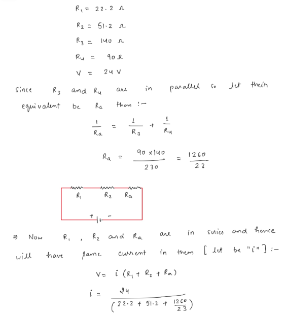
An ideal emf device (24.0 V) is connected to a set of resistors as shown in...
Two ideal emf devices are connected to a set of resistors as shown in the figure...
 Two ideal emf devices are connected to a set of resistors as
shown in the figure below. If E1 = 7.50 V, R1 = 12.00 ?, R2 = 4.50
?, R3 = 14.50 ?, R4 = 19.50 ?, and the current through R4 is 0.240
A, what is the emf E2?
4 1R
Two ideal emf devices are connected to a set of resistors as
shown in the figure below. If E1 = 7.50 V, R1 = 12.00 ?, R2 = 4.50
?, R3 = 14.50 ?, R4 = 19.50 ?, and the current through R4 is 0.240
A, what is the emf E2?
4 1R
15. N In Figure P29.15, three resistors are connected to an ideal E = 14.8 V....
 15. N In Figure P29.15, three resistors are connected to an ideal E = 14.8 V. Ri-13.4 Ω, R.-20.5 Ω, and emf device, where a. What is the current through each resistor? b. What is the voltage across cach resistor? c. How much power is consumed by each resistor and by the emf device?
Four resistors are connected to a battery as shown in the figure
 Four resistors are connected to a battery as shown in the figure. The current through the battery is I, the battery's electromotive force (emf) is ℰ=2.20 V, and the resistor values are R1=R, R2=2 R, R3=4 R, and R4=3 R. Find the voltages across each resistor.
An ideal emf device with = 5.00 V is connected to two resistors in series. One...
An ideal emf device with = 5.00 V is connected to two resistors in series. One of the resistors has a resistance of 155 Ω, and the other has unknown resistance R. If the current through the emf device is 0.0135 A, what is the resistance R?
2. A set of resistors are connected to a 10.0 V battery as shown in the...
 2. A set of resistors are connected to a 10.0 V battery as shown in the figure below. The capacitors have values of R1 = 300 2, R2 = 150 12, R3 = 250, R4 = 100 2 and Rs = 200 22. Determine the value of the following quantities (a) when the switch is open. • the current flowing through each resistor, • the potential drop across each resistor, and • the power dissipated in each resistor. (b) when...
Four resistors are connected to a battery as shown in the figure. The current in the...
 Four resistors are connected to a battery as shown in the
figure. The current in the battery is I, the battery emf is ? =
11.55 V, and the resistor values are R1 = R, R2 = 2R, R3 = 4R, R4 =
3R. Find the voltages across each resistor.v1=v2=v3=v4=
Four resistors are connected to a battery as shown in the
figure. The current in the battery is I, the battery emf is ? =
11.55 V, and the resistor values are R1 = R, R2 = 2R, R3 = 4R, R4 =
3R. Find the voltages across each resistor.v1=v2=v3=v4=
Consider the circuit shown in the figure(Figure 1). Suppose thefour resistors in this circuit have...
 Consider the circuit shown in the figure(Figure 1). Suppose the
four resistors in this circuit have the values R1 = 10 Ω , R2 = 6.6
Ω , R3 = 6.1 Ω , and R4 = 14 Ω , and that the emf of the battery is
E = 18 V .Find the current through each resistor using the rules for
series and parallel resistors.Find the current through each resistor using Kirchhoff's
rules.
Consider the circuit shown in the figure(Figure 1). Suppose the
four resistors in this circuit have the values R1 = 10 Ω , R2 = 6.6
Ω , R3 = 6.1 Ω , and R4 = 14 Ω , and that the emf of the battery is
E = 18 V .Find the current through each resistor using the rules for
series and parallel resistors.Find the current through each resistor using Kirchhoff's
rules.
The emf in the figure below is 4.50 V. The resistances are R1 = 25.5 Ω,...
 The emf in the figure below is 4.50 V. The resistances are R1 = 25.5 Ω, R2 = 27.5 Ω, and R3 following 38.5 Ω. Find the Ri R2 R3 (a) the current in each resistor (Give your answers to at least three significant figures.) (b) the power consumed by each resistor P2= (c) the power supplied by the emf device
Three resistors are connected to an ideal battery (no internal resistance) as shown. The values are:...
Three resistors are connected to an ideal battery (no internal resistance) as shown. The values are: EMF = 19 V R1 = 39 Ohms R2 = 70 Ohms R3 = 66 Ohms What is the total power output by the battery? Hint: You might consider the current through each individual resistor.
Two resistors are connected in series with a battery whose EMF is 35 V as shown...
 Two resistors are connected in series with a battery whose EMF is 35 V as shown in the figure below. The resistances of resistor 1 is R1=37 and of resistor 2 is R2 = 57 2. What is the value of the current flowing through the circuit? R1 E R2 In the figure below bulb B is brighter than bulb C which is brighter than bulb A. Rank the magnitudes of the potential differences (voltages) across the bulbs, largest first...
 Two ideal emf devices are connected to a set of resistors as
shown in the figure below. If E1 = 7.50 V, R1 = 12.00 ?, R2 = 4.50
?, R3 = 14.50 ?, R4 = 19.50 ?, and the current through R4 is 0.240
A, what is the emf E2?
4 1R
Two ideal emf devices are connected to a set of resistors as
shown in the figure below. If E1 = 7.50 V, R1 = 12.00 ?, R2 = 4.50
?, R3 = 14.50 ?, R4 = 19.50 ?, and the current through R4 is 0.240
A, what is the emf E2?
4 1R
 15. N In Figure P29.15, three resistors are connected to an ideal E = 14.8 V. Ri-13.4 Ω, R.-20.5 Ω, and emf device, where a. What is the current through each resistor? b. What is the voltage across cach resistor? c. How much power is consumed by each resistor and by the emf device?
 2. A set of resistors are connected to a 10.0 V battery as shown in the figure below. The capacitors have values of R1 = 300 2, R2 = 150 12, R3 = 250, R4 = 100 2 and Rs = 200 22. Determine the value of the following quantities (a) when the switch is open. • the current flowing through each resistor, • the potential drop across each resistor, and • the power dissipated in each resistor. (b) when...
 Four resistors are connected to a battery as shown in the
figure. The current in the battery is I, the battery emf is ? =
11.55 V, and the resistor values are R1 = R, R2 = 2R, R3 = 4R, R4 =
3R. Find the voltages across each resistor.v1=v2=v3=v4=
Four resistors are connected to a battery as shown in the
figure. The current in the battery is I, the battery emf is ? =
11.55 V, and the resistor values are R1 = R, R2 = 2R, R3 = 4R, R4 =
3R. Find the voltages across each resistor.v1=v2=v3=v4=
 Consider the circuit shown in the figure(Figure 1). Suppose the
four resistors in this circuit have the values R1 = 10 Ω , R2 = 6.6
Ω , R3 = 6.1 Ω , and R4 = 14 Ω , and that the emf of the battery is
E = 18 V .Find the current through each resistor using the rules for
series and parallel resistors.Find the current through each resistor using Kirchhoff's
rules.
Consider the circuit shown in the figure(Figure 1). Suppose the
four resistors in this circuit have the values R1 = 10 Ω , R2 = 6.6
Ω , R3 = 6.1 Ω , and R4 = 14 Ω , and that the emf of the battery is
E = 18 V .Find the current through each resistor using the rules for
series and parallel resistors.Find the current through each resistor using Kirchhoff's
rules.
 The emf in the figure below is 4.50 V. The resistances are R1 = 25.5 Ω, R2 = 27.5 Ω, and R3 following 38.5 Ω. Find the Ri R2 R3 (a) the current in each resistor (Give your answers to at least three significant figures.) (b) the power consumed by each resistor P2= (c) the power supplied by the emf device
 Two resistors are connected in series with a battery whose EMF is 35 V as shown in the figure below. The resistances of resistor 1 is R1=37 and of resistor 2 is R2 = 57 2. What is the value of the current flowing through the circuit? R1 E R2 In the figure below bulb B is brighter than bulb C which is brighter than bulb A. Rank the magnitudes of the potential differences (voltages) across the bulbs, largest first...
Most questions answered within 3 hours.
-
1. why is toluene a stronger nucleophile than benzene?
2.why is phenol a stronger nucleophile than...
asked 12 minutes ago -
4. How can you solve for the density of the liquid from the
slope? Please show...
asked 12 minutes ago -
when 2053 j of heat is added to 46.3 g of hexane C6H14 the
temperature increases...
asked 36 minutes ago -
I need new and unique answers, please. (Use your own words,
don't copy and paste), Please...
asked 39 minutes ago -
MCL 445.111 et seq. deals with Home Solicitation Sales.
MCL stands for Michigan Compiled Laws which...
asked 30 minutes ago -
Which of the following items may not create an NOL?
a.
sole proprietorship loss
b.
personal...
asked 35 minutes ago -
A hypothetical solution forms between a solid and a liquid. The
values of the thermodynamic quantities...
asked 33 minutes ago -
a)An ideal heat pump is being considered for use in heating an
environment with a temperature...
asked 36 minutes ago -
.
Convert the following pairs of voltage and current waveforms to
phasor form. Each pair of...
asked 37 minutes ago -
A 6.5 cm diameter ball has a terminal speed of 22 m/s. What is
the ball's...
asked 51 minutes ago -
Name two areas of the human body with the highest concentration
of lymph nodes and speculate...
asked 55 minutes ago -
Angel Corporation has $10,000,000 of
8.0% 25 year bonds dated May 1, 2018 with interest payable...
asked 1 hour ago