
Homework Answers


Add Answer to:
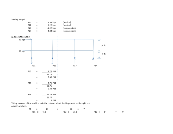
HW#3 HWK 3: For the given frame, calculate the axial and shear forces and the moments...
compute the bending moments, shear forces and axial forces for the frame shown, using portal method....
 compute the bending moments, shear forces and axial
forces for the frame shown, using portal method.
3535 ft 35 ft Problem 15.15 5.16 30 kN D H 60 kN 0NG C G 60 kN Problem 15.16
compute the bending moments, shear forces and axial
forces for the frame shown, using portal method.
3535 ft 35 ft Problem 15.15 5.16 30 kN D H 60 kN 0NG C G 60 kN Problem 15.16
For Problems 15.15 through 15.18, compute the bending moments, shear forces, and axial forces for all...
 For Problems 15.15 through 15.18, compute the bending moments, shear forces, and axial forces for all of the members of the frames shown using the portal method. All joints are assumed to be rigid. P15.15 (Ans: MGF -210 k.ft, MFJ 280 k-ft) 30 k 60 k 60 k MIL Problem 15.15
1. (60 points) Draw axial, shear, and bending moment diagrams for the frame shown below. Draw...
 1. (60 points) Draw axial, shear, and bending moment diagrams for the frame shown below. Draw one set of P, V, and M diagrams for Column AB, one set for Beam BE, and one set for Column DF. There is a fixed support at A and applied forces and moments as shown below. 500 lb 500 lb 5 k-ft 5 k-ft D 5 k-ft B 10 10' 10' E 500 lb/ft 10' 10' 5k s tiskt 5 k-ft 1k 2....
Problem #1: TO SELECT THE MOST ECONOMICAL Wio SHAPE COLUMN ZO FEET IN HEIGHT SUPPORT AH...
 Problem #1: TO SELECT THE MOST ECONOMICAL Wio SHAPE COLUMN ZO FEET IN HEIGHT SUPPORT AH AXIAL LORD OF 370 KIPS using soksi STEEL! ASSUME A FIXED BASE ANDA PINGED TOP (CASE C) WIDE FLANGE SHAPES HP Axis Y-Y Theoretical Dimensions and Properties for Designing Flange Axis X-X | Weight Area Depth Web Section per of of Thick- Thick- Number Foot Section Section Width S 'T Sy Ty ness ness < * A by tw in. in. in.' in. in....
 compute the bending moments, shear forces and axial
forces for the frame shown, using portal method.
3535 ft 35 ft Problem 15.15 5.16 30 kN D H 60 kN 0NG C G 60 kN Problem 15.16
compute the bending moments, shear forces and axial
forces for the frame shown, using portal method.
3535 ft 35 ft Problem 15.15 5.16 30 kN D H 60 kN 0NG C G 60 kN Problem 15.16
 For Problems 15.15 through 15.18, compute the bending moments, shear forces, and axial forces for all of the members of the frames shown using the portal method. All joints are assumed to be rigid. P15.15 (Ans: MGF -210 k.ft, MFJ 280 k-ft) 30 k 60 k 60 k MIL Problem 15.15
 1. (60 points) Draw axial, shear, and bending moment diagrams for the frame shown below. Draw one set of P, V, and M diagrams for Column AB, one set for Beam BE, and one set for Column DF. There is a fixed support at A and applied forces and moments as shown below. 500 lb 500 lb 5 k-ft 5 k-ft D 5 k-ft B 10 10' 10' E 500 lb/ft 10' 10' 5k s tiskt 5 k-ft 1k 2....
 Problem #1: TO SELECT THE MOST ECONOMICAL Wio SHAPE COLUMN ZO FEET IN HEIGHT SUPPORT AH AXIAL LORD OF 370 KIPS using soksi STEEL! ASSUME A FIXED BASE ANDA PINGED TOP (CASE C) WIDE FLANGE SHAPES HP Axis Y-Y Theoretical Dimensions and Properties for Designing Flange Axis X-X | Weight Area Depth Web Section per of of Thick- Thick- Number Foot Section Section Width S 'T Sy Ty ness ness < * A by tw in. in. in.' in. in....
Most questions answered within 3 hours.
-
A rotating space station is said to create “artificial
gravity”—a loosely-defined term used for an acceleration...
asked 9 minutes ago -
The following MIPS branching pseudo instruction
bge $s0, $s1, Label # branch to Label if $s0...
asked 11 minutes ago -
In cation exchange chromatography, the beads are covalently
linked to a ________chemical and a ______________ ion...
asked 10 seconds from now -
A block in the shape of a rectangular solid has a
cross-sectional area of 4.58 cm2...
asked 13 minutes ago -
Which of the following countries has abolished tied aid?
Select one:
a. France
b. The United...
asked 9 minutes ago -
ASAP using c++ vectors Create a vector of characters and ask the
user to enter their...
asked 28 minutes ago -
On December 31, 2018, Wellstone Company reported net income of
$76,000 and sales of $215,000. The...
asked 27 minutes ago -
Question #1
Consider the following potential investment, which has the same
risk as a firm’s other...
asked 29 minutes ago -
Globalization = Standardization + Localization: What does this
equation really mean about optimizing a firm’s offerings...
asked 27 minutes ago -
The A&M Hobby Shop carries a line of radio-controlled model
racing cars. Demand for the cars...
asked 1 hour ago -
Suppose that the recovery period, in days, for patients having
back surgery is normally distributed with...
asked 40 minutes ago -
When aqueous solutions of potassium cyanide and hydrochloric
acid are mixed, an aqueous solution of potassium...
asked 1 hour ago