
Homework Answers
![var Sx20x10-3 +1) - sxorb Vs Is] 2oNo3 SX20X10-3 Vs (5) it Sx28x183 * due to viritual short circuit concept. [va = Vb anos 1+](http://img.homeworklib.com/questions/c0fe9bf0-701d-11ec-ace6-a95aec6b43ad.png?x-oss-process=image/resize,w_560)
Add Answer to:
*Problem 14.8-31 The input to this circuit is the source voltage, vs(t). The output is the...
Question 2 (10%) The input to the circuit shown in Fig. 2 is the voltage source...
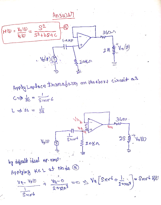
 Question 2 (10%) The input to the circuit shown in Fig. 2 is the voltage source vs(t). The output is the voltage across two open terminals, vo(). If v()-3-(t) V, the output is the voltage vo()-10+Se30* V for 20. Determine the values of Ri and R2. 2 sa) olt) Fig. 2
Problem 10.10-1 72 kS2 The input to this circuit is the voltage source voltage given by...
 Problem 10.10-1 72 kS2 The input to this circuit is the voltage source voltage given by v(t) 2.65cos 310t-15° v 0.5HF The output is the voltage Vo(t)-Acos(310 t + ?) v vi0) ou) where A and ? are constants such that A > 0 and-180° < ? < 180°. Determine the values of the constants A and ?: | V and ?
8–31 A voltage vs(t) = 50 cos (5000t) V is applied to the circuit in Figure...
 8–31 A voltage vs(t) = 50 cos (5000t) V is applied to the circuit in Figure P8–31. (a) Convert the circuit into the phasor domain. (b) Find the phasor current flowing through the circuit and the phasor voltages across the inductor and the resistor. (c) Plot all three phasors from (b) on a phasor diagram. Describe if the current leads or lags the inductor voltage. i(t) 50 22 25 mH 00 + VL(t) - + Vr(t)- vs(t) (+) FIGURE P8-31
H 3. A voltage source of known voltage Vo is connected in series with a switch...
 H 3. A voltage source of known voltage Vo is connected in series with a switch and a known resistor Ro and an unknown inductor Lx as shown. The switch is closed at time t 0, and the voltage VL across Lx is monitored by the oscilloscope. Ro Lx Osc (a) Sketch the waveform of Vi vs t as seen on the oscilloscope. (b) If at a known time i, VL V3, what is L? Express your answer in terms...
1.29 The voltage source of the circuit shown in Fig. P1.29 is given by vs(t) =...
 1.29 The voltage source of the circuit shown in Fig. P1.29 is given by vs(t) = 25 cos(4 x 10⁴t - 45°) (V). Obtain an expression for il(t), the current flowing through the inductor IR vs() R23 R1 = 20 12, R2 = 30 12, L = 0.4 mH
The input to the circuit shown in Fig. 2 is the voltage source v(t). The output...
 The input to the circuit shown in Fig. 2 is the voltage source v(t). The output is the voltage across the capacitor, v(t). Determine the output of this circuit as a function of time t when the input is v.(t)-8+12u(t) V 40 18 s(t) 160 Fig. 2
The input to the below op-amp circuit is the source voltage vi(t) and the response is...
 The input to the below op-amp circuit is the source voltage vi(t) and the response is the voltage across Rư, vo(t). Design this circuit to satisfy the following two specifications: (a) The phase shift at w = 1000 rad/s is 225 degree. (b) The gain at high frequencies is 10. Ri C = 0.1 uF vilo o Rız volt)
Chapter 31, Problem 045 (a) In an RLC circuit, can the amplitude of the voltage across...
 Chapter 31, Problem 045 (a) In an RLC circuit, can the amplitude of the voltage across an inductor be greater than the amplitude of the generator emf? (b) Consider an RLC circuit with driving emf amplitude Em-8 V resistance R = 9 Ω, inductance L = 1.0 H, and capacitance C = 1.1 μF. Find the amplitude of the voltage across the inductor at resonance (b) Number Units the tolerance is +/-596
A series RLC circuit is connected to an independent voltage source Vs = 160 V with...
 A series RLC circuit is connected to an independent voltage source Vs = 160 V with a switch closing at t = 0. If R = 4.8 kohm, L = 4 mH, C = 0.25 mF, find the s-domain and time domain (when t > 0) representations of the current, a) if there is no stored energy in the circuit. b) if the 100 mJ stored energy is equally shared between the inductor and the capacito
find iL(t) For the circuit shown below, Vs - 200V, R = 3k32, R2 = 5k82,...
 find iL(t)
For the circuit shown below, Vs - 200V, R = 3k32, R2 = 5k82, C-0.125uF and L=8mH. Find (a) the initial voltage across the capacitor, ve(0), (b) the initial current through the inductor, iL(0), (C) the damping coefficient a and resonant frequency 0., (d) the initial condition dv/dt=0+, (e) the voltage across the capacitor ve(t) for t0,(1) the initial condition diu/dt)-0+, and (g) the current through the inductor il(t) for t>0. Vg 20V 2 souw Xol25x10 = 800...
find iL(t)
For the circuit shown below, Vs - 200V, R = 3k32, R2 = 5k82, C-0.125uF and L=8mH. Find (a) the initial voltage across the capacitor, ve(0), (b) the initial current through the inductor, iL(0), (C) the damping coefficient a and resonant frequency 0., (d) the initial condition dv/dt=0+, (e) the voltage across the capacitor ve(t) for t0,(1) the initial condition diu/dt)-0+, and (g) the current through the inductor il(t) for t>0. Vg 20V 2 souw Xol25x10 = 800...
 Question 2 (10%) The input to the circuit shown in Fig. 2 is the voltage source vs(t). The output is the voltage across two open terminals, vo(). If v()-3-(t) V, the output is the voltage vo()-10+Se30* V for 20. Determine the values of Ri and R2. 2 sa) olt) Fig. 2
 Problem 10.10-1 72 kS2 The input to this circuit is the voltage source voltage given by v(t) 2.65cos 310t-15° v 0.5HF The output is the voltage Vo(t)-Acos(310 t + ?) v vi0) ou) where A and ? are constants such that A > 0 and-180° < ? < 180°. Determine the values of the constants A and ?: | V and ?
 8–31 A voltage vs(t) = 50 cos (5000t) V is applied to the circuit in Figure P8–31. (a) Convert the circuit into the phasor domain. (b) Find the phasor current flowing through the circuit and the phasor voltages across the inductor and the resistor. (c) Plot all three phasors from (b) on a phasor diagram. Describe if the current leads or lags the inductor voltage. i(t) 50 22 25 mH 00 + VL(t) - + Vr(t)- vs(t) (+) FIGURE P8-31
 H 3. A voltage source of known voltage Vo is connected in series with a switch and a known resistor Ro and an unknown inductor Lx as shown. The switch is closed at time t 0, and the voltage VL across Lx is monitored by the oscilloscope. Ro Lx Osc (a) Sketch the waveform of Vi vs t as seen on the oscilloscope. (b) If at a known time i, VL V3, what is L? Express your answer in terms...
 1.29 The voltage source of the circuit shown in Fig. P1.29 is given by vs(t) = 25 cos(4 x 10⁴t - 45°) (V). Obtain an expression for il(t), the current flowing through the inductor IR vs() R23 R1 = 20 12, R2 = 30 12, L = 0.4 mH
 The input to the circuit shown in Fig. 2 is the voltage source v(t). The output is the voltage across the capacitor, v(t). Determine the output of this circuit as a function of time t when the input is v.(t)-8+12u(t) V 40 18 s(t) 160 Fig. 2
 The input to the below op-amp circuit is the source voltage vi(t) and the response is the voltage across Rư, vo(t). Design this circuit to satisfy the following two specifications: (a) The phase shift at w = 1000 rad/s is 225 degree. (b) The gain at high frequencies is 10. Ri C = 0.1 uF vilo o Rız volt)
 Chapter 31, Problem 045 (a) In an RLC circuit, can the amplitude of the voltage across an inductor be greater than the amplitude of the generator emf? (b) Consider an RLC circuit with driving emf amplitude Em-8 V resistance R = 9 Ω, inductance L = 1.0 H, and capacitance C = 1.1 μF. Find the amplitude of the voltage across the inductor at resonance (b) Number Units the tolerance is +/-596
 A series RLC circuit is connected to an independent voltage source Vs = 160 V with a switch closing at t = 0. If R = 4.8 kohm, L = 4 mH, C = 0.25 mF, find the s-domain and time domain (when t > 0) representations of the current, a) if there is no stored energy in the circuit. b) if the 100 mJ stored energy is equally shared between the inductor and the capacito
 find iL(t)
For the circuit shown below, Vs - 200V, R = 3k32, R2 = 5k82, C-0.125uF and L=8mH. Find (a) the initial voltage across the capacitor, ve(0), (b) the initial current through the inductor, iL(0), (C) the damping coefficient a and resonant frequency 0., (d) the initial condition dv/dt=0+, (e) the voltage across the capacitor ve(t) for t0,(1) the initial condition diu/dt)-0+, and (g) the current through the inductor il(t) for t>0. Vg 20V 2 souw Xol25x10 = 800...
find iL(t)
For the circuit shown below, Vs - 200V, R = 3k32, R2 = 5k82, C-0.125uF and L=8mH. Find (a) the initial voltage across the capacitor, ve(0), (b) the initial current through the inductor, iL(0), (C) the damping coefficient a and resonant frequency 0., (d) the initial condition dv/dt=0+, (e) the voltage across the capacitor ve(t) for t0,(1) the initial condition diu/dt)-0+, and (g) the current through the inductor il(t) for t>0. Vg 20V 2 souw Xol25x10 = 800...
Most questions answered within 3 hours.
-
2) You are given the task of finding a representation for a
circle in a drawing...
asked 37 minutes ago -
STUDY QUESTION: Does use of diet drug fen-phen
(fenfluramine-phentermine) cause valvular heart disease?
HINT: Valvular heart...
asked 28 minutes ago -
1. An object weighing 40 N rests on a surface. The coefficient
of friction is 0.35....
asked 1 hour ago -
Investor company owns 35% of investee company voting stock and
accounts for the investment under the...
asked 2 hours ago -
The number of major faults on a randomly chosen 1 km stretch of
highway has a...
asked 3 hours ago -
Consider the competitive environment of Starbuck's, Progressive
Insurance, a manufacturing firm with low turnover, or a...
asked 4 hours ago -
3. Gains from trade
Consider two neighbouring island countries called Euphoria and
Contente. They each have...
asked 5 hours ago -
A business executive has the option to invest money in two
plans: Plan A guarantees that...
asked 8 hours ago -
Hello, can someone please help me answer this question?
How much heat is absorbed by a...
asked 8 hours ago -
. A marketing researcher conducted a survey of 25 shoppers
randomly selected at the local mall...
asked 8 hours ago -
Create an comprehensive response to the
following:
Antimicrobial agents work on a multitude of microbes (bacteria,...
asked 8 hours ago -
6.13 LAB: Step counter. Section 6.3.
A pedometer treats walking 2,000 steps as walking 1 mile....
asked 8 hours ago