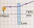
A ray from an object passes through a thin lens, as shown in the figure. What...
Homework Answers
As we see in the figure the rays comings from the object gets diverge when it passes through the lens So it is Concave lens because it is diverging in nature so it must be diverging lens
So the correct option is A & tge lens is concave lens
Add Answer to:
A ray from an object passes through a thin lens, as shown in the figure. What...
3. Figure shows an object and its image formed by a thin lens. (a) What is...
 3. Figure shows an object and its image formed by a thin lens. (a) What is the focal length of the lens and what type of lens (converging or diverging) is it? (b) What is the height of the image? Is it real or virtual? Draw a principal-ray diagram showing the formation of the image. -35.0 cm- Optic Object 15 Lens El crn Image 4. Figure shows an object and its image formed by a thin lens. (a) What is...
An object is located at a distance of 6 cm from a thin converging lens with...
An object is located at a distance of 6 cm from a thin converging lens with focal length of 2 cm. A diverging lens is located 4 cm from the converging lens and 10 cm from the object. The diverging lens has a focal length of -3 cm. Note: To handle a multiple lens system, we treat them independently. We first find the image created by the first lens. We then use the image from the first lens to act...
(2) An object is located at a distance of 4 cm from a thin converging lens...
 (2) An object is located at a distance of 4 cm from a thin converging lens with focal length of 2 cm. A diverging lens is located 3 cm from the converging lens and 7 cm from the object. The diverging lens has a focal length of -2 cm. Use the thin lens equation to predict the following (a) Location of the final image? to the object? (c) Is the final image real or virtual?
help me Question 3) An object with height 1.sotem) (the thick arrow in de converging converging lens. There is a distance from each lens to its own focal point is 15.olem diagram) is 33.0fem] t...
 help me
Question 3) An object with height 1.sotem) (the thick arrow in de converging converging lens. There is a distance from each lens to its own focal point is 15.olem diagram) is 33.0fem] to the left of a diverging lens that is 50.0[cm] to the right of the converging lens. The neha he scale is different in the vertical and horizontal directions (Be careful about sign conventions) DivergiNg Lens Converging Lens Object 1.50 cm 15.0 cm-15.0cm 15.0cm -5.0cm 33.3...
help me
Question 3) An object with height 1.sotem) (the thick arrow in de converging converging lens. There is a distance from each lens to its own focal point is 15.olem diagram) is 33.0fem] to the left of a diverging lens that is 50.0[cm] to the right of the converging lens. The neha he scale is different in the vertical and horizontal directions (Be careful about sign conventions) DivergiNg Lens Converging Lens Object 1.50 cm 15.0 cm-15.0cm 15.0cm -5.0cm 33.3...
2. Two thin lenses, one a converging lens and the other a diverging lens, are arated...
 2. Two thin lenses, one a converging lens and the other a diverging lens, are arated by 1.00 m along the same principal axis, as shown in the figure. The magnitude of the focal length of the converging lens is 25 cm, while the magnitude of the focal length of the diverging lens is 40 em. An object 8,25 cm tall is placed 35 cm to the left of the converging lens. (a) Where is the final image produced by...
Figure 3: Problem 12: light ray refracted by a thin convergent lens located at x = 0.
 Figure 3: Problem 12: light ray refracted by a thin convergent lens located at x = 0. A ray of light is shown in Fig. 3 as it passes through a convergent thin lens. If the grid lines are 1.0 cm apart in the figure, this lens has a focal length of A) 1.58 cm B) 3.17 cm C) -6.34cm D) 6.34 cm E) –1.58 cm
A 4.0 cm tall object is 5.0 cm in front of a diverging lens with a focal length of -6.0 cm. A converging lens with a fo...
 A 4.0 cm tall object is 5.0 cm in front of a diverging lens with a focal length of -6.0 cm. A converging lens with a focal length of 6.0 cm is located 8.0 cm behind the diverging lens. (As viewed from the side, from left to right, the sequence is object - diverging lens - converging lens - observer. Rays then travel from left to right through the system.) (a) Use ray tracing to draw image 1 and image...
Thin lenses. Object O stands on the central axis of a thin symmetric lens. For this...
 Thin lenses. Object O stands on the central
axis of a thin symmetric lens. For this situation, each problem in
the table (below) gives object distance p (centimeters),
the type of lens (C stands for converging and D for diverging), and
then the distance (centimeters, without proper sign) between a
focal point and the lens. Find (a) the image
distance i and (b) the lateral
magnification m of the object, including signs. Also,
determine whether the image is (c) real...
Thin lenses. Object O stands on the central
axis of a thin symmetric lens. For this situation, each problem in
the table (below) gives object distance p (centimeters),
the type of lens (C stands for converging and D for diverging), and
then the distance (centimeters, without proper sign) between a
focal point and the lens. Find (a) the image
distance i and (b) the lateral
magnification m of the object, including signs. Also,
determine whether the image is (c) real...
Part A: A diverging lens has of focal length of 15.0 cm. An object is placed 21 cm to the left of the lens. a) draw a ray diagram showing the situation. b) find the location of the image produced by t...
Part A: A diverging lens has of focal length of 15.0 cm. An object is placed 21 cm to the left of the lens. a) draw a ray diagram showing the situation. b) find the location of the image produced by the lens (mind the signs). Part B: A converging lens is located 30 cm to the right of the previously mentioned diverging lens (part A). As a result, the image you found in part (a) is now instead located...
Draw a ray diagram for the following situation (an object far from the lens) involving a...
 Draw a ray diagram for the following situation (an object far from the lens) involving a diverging lens. The ray tracing needs to have the three principal rays. Also, draw the image on the ray diagram where the three principal rays converge. Refer to Section 26.4 of Serway & Jewett for further guidance on how to construct principal rays. Use a ruler to measure the object distances, image distances, and focal lengths for the ray diagram. Then, verify that your...
 3. Figure shows an object and its image formed by a thin lens. (a) What is the focal length of the lens and what type of lens (converging or diverging) is it? (b) What is the height of the image? Is it real or virtual? Draw a principal-ray diagram showing the formation of the image. -35.0 cm- Optic Object 15 Lens El crn Image 4. Figure shows an object and its image formed by a thin lens. (a) What is...
 (2) An object is located at a distance of 4 cm from a thin converging lens with focal length of 2 cm. A diverging lens is located 3 cm from the converging lens and 7 cm from the object. The diverging lens has a focal length of -2 cm. Use the thin lens equation to predict the following (a) Location of the final image? to the object? (c) Is the final image real or virtual?
 help me
Question 3) An object with height 1.sotem) (the thick arrow in de converging converging lens. There is a distance from each lens to its own focal point is 15.olem diagram) is 33.0fem] to the left of a diverging lens that is 50.0[cm] to the right of the converging lens. The neha he scale is different in the vertical and horizontal directions (Be careful about sign conventions) DivergiNg Lens Converging Lens Object 1.50 cm 15.0 cm-15.0cm 15.0cm -5.0cm 33.3...
help me
Question 3) An object with height 1.sotem) (the thick arrow in de converging converging lens. There is a distance from each lens to its own focal point is 15.olem diagram) is 33.0fem] to the left of a diverging lens that is 50.0[cm] to the right of the converging lens. The neha he scale is different in the vertical and horizontal directions (Be careful about sign conventions) DivergiNg Lens Converging Lens Object 1.50 cm 15.0 cm-15.0cm 15.0cm -5.0cm 33.3...
 2. Two thin lenses, one a converging lens and the other a diverging lens, are arated by 1.00 m along the same principal axis, as shown in the figure. The magnitude of the focal length of the converging lens is 25 cm, while the magnitude of the focal length of the diverging lens is 40 em. An object 8,25 cm tall is placed 35 cm to the left of the converging lens. (a) Where is the final image produced by...
 A 4.0 cm tall object is 5.0 cm in front of a diverging lens with a focal length of -6.0 cm. A converging lens with a focal length of 6.0 cm is located 8.0 cm behind the diverging lens. (As viewed from the side, from left to right, the sequence is object - diverging lens - converging lens - observer. Rays then travel from left to right through the system.) (a) Use ray tracing to draw image 1 and image...
 Thin lenses. Object O stands on the central
axis of a thin symmetric lens. For this situation, each problem in
the table (below) gives object distance p (centimeters),
the type of lens (C stands for converging and D for diverging), and
then the distance (centimeters, without proper sign) between a
focal point and the lens. Find (a) the image
distance i and (b) the lateral
magnification m of the object, including signs. Also,
determine whether the image is (c) real...
Thin lenses. Object O stands on the central
axis of a thin symmetric lens. For this situation, each problem in
the table (below) gives object distance p (centimeters),
the type of lens (C stands for converging and D for diverging), and
then the distance (centimeters, without proper sign) between a
focal point and the lens. Find (a) the image
distance i and (b) the lateral
magnification m of the object, including signs. Also,
determine whether the image is (c) real...
 Draw a ray diagram for the following situation (an object far from the lens) involving a diverging lens. The ray tracing needs to have the three principal rays. Also, draw the image on the ray diagram where the three principal rays converge. Refer to Section 26.4 of Serway & Jewett for further guidance on how to construct principal rays. Use a ruler to measure the object distances, image distances, and focal lengths for the ray diagram. Then, verify that your...
Most questions answered within 3 hours.
-
Week 10 - Professional Memo Assignment
Professional Memo Assignment
Your mission for this week, should you...
asked 2 minutes ago -
Write a Python program that stores the data for each
player on the team, and it...
asked 12 minutes ago -
In
the last 3 months, mike never knows when he is going to get his
allowance...
asked 36 minutes ago -
Is Ca(OH)2 a Bronsted base, Lewis base, or both? Why?
asked 26 minutes ago -
1A- Why don’t voters complain about U.S. tariffs on imported
sugar?
Because sugar is only a...
asked 35 minutes ago -
Cash Payback Period
Primera Banco is evaluating two capital investment proposals for
a drive-up ATM kiosk,...
asked 33 minutes ago -
Create a button in Swift (Xcode) that will create a charge,
create a charge using Stripe's...
asked 33 minutes ago -
The reaction rate of CO and NO2 in the reaction
CO(g) + NO2(g) → CO2(g) +...
asked 35 minutes ago -
Imagine that a chemist puts 6.40 mol each of
C3H8 and O2 in a 1.00-L container...
asked 52 minutes ago -
How much money should be invested today in order to have $8340
at the end of...
asked 56 minutes ago -
You are conducting research for a hospital and issue a survey to
patients.
Based on the...
asked 56 minutes ago -
What might be a negative mutation that would hinder the
bug population?
asked 1 hour ago