
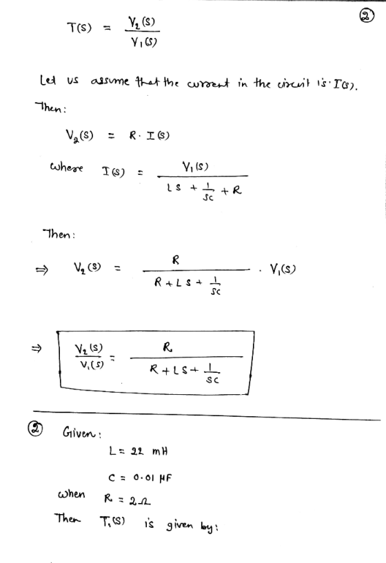
Q1. Write equations for ?(?) = ' in the s domain in terms of the symbolic parameters C, L, and R.
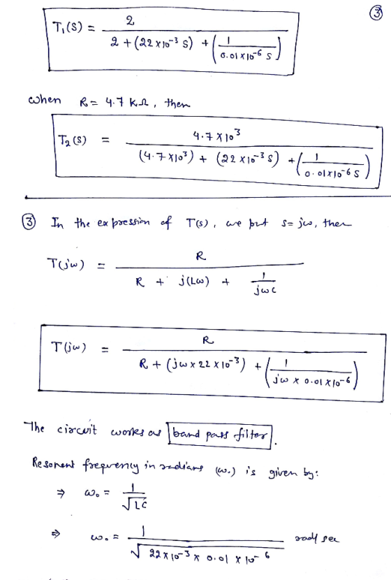
Q2. Let L=22mH, C = 0.01μF. We will check out what happens for two values of R: R= 2Ω and R= 4.7kΩ. Substitute in these values for the inductor, capacitor and resistors and find numerical expressions for T1(s) and T2(s).
Q3. In the expression for T(s), substitute s=jw to get the sinusoidal steady-state responses of the circuit as a function of the (radian) frequency w. Will this circuit be a high pass, low pass, or bandpass filter? What is the resonant frequency, both in radian frequency w0 and frequency f0?
Homework Answers


Add Answer to:
Q1. Write equations for ?(?) = ' in the s domain in terms of the
symbolic...
7. A sinusoidal voltage Vt) (200V) sin(ot) is applied to a series RLC circuit with, L=10...
 7. A sinusoidal voltage Vt) (200V) sin(ot) is applied to a series RLC circuit with, L=10 mH, C=100 nF and R=20.0 2. a) Find the resonant frequency. b) Find the amplitude of the current at resonance. c) Find the amplitude of the voltage across the inductor at the resonant frequency
Please help with the following question correctly for thumbs up! 5. + -11 points SerPSE 10...
 Please help with the following question correctly for thumbs
up!
5. + -11 points SerPSE 10 32.7.P.026. A series RLC circuit has components with the following values: L = 18.0 mH, C = 80.0 nF, R = 30.0 2, and AVmax = 100 V, with Av = AV may sin wt. (a) Find the resonant frequency of the circuit. kHz (b) Find the amplitude of the current at the resonant frequency. (c) Find the Q of the circuit. (d) Find...
Please help with the following question correctly for thumbs
up!
5. + -11 points SerPSE 10 32.7.P.026. A series RLC circuit has components with the following values: L = 18.0 mH, C = 80.0 nF, R = 30.0 2, and AVmax = 100 V, with Av = AV may sin wt. (a) Find the resonant frequency of the circuit. kHz (b) Find the amplitude of the current at the resonant frequency. (c) Find the Q of the circuit. (d) Find...
Help A series RLC circuit has components with the following values: L = 16.0 mH. C...
 Help
A series RLC circuit has components with the following values: L = 16.0 mH. C = 82.0 nF, R = 15.0 ohm, and Delta V_max = 100 V, with Delta v = Delta V_max sin omega t. Find the resonant frequency of the circuit. 4.3939e03 Resonance occurs when the impedance is at a minimum. kHz Find the amplitude of the current at the resonant frequency. 6.67 A Find the Q of the circuit. 2.68 How is the Q related...
Help
A series RLC circuit has components with the following values: L = 16.0 mH. C = 82.0 nF, R = 15.0 ohm, and Delta V_max = 100 V, with Delta v = Delta V_max sin omega t. Find the resonant frequency of the circuit. 4.3939e03 Resonance occurs when the impedance is at a minimum. kHz Find the amplitude of the current at the resonant frequency. 6.67 A Find the Q of the circuit. 2.68 How is the Q related...
(a) For the circuit of Figure 4, assuming a sinusoidal is(t) (0) Prove that the resonant frequeney is given by o- (3 marks) LC (ii) If the total admittance at resonance is 20 ms (seen by the source)...
 (a) For the circuit of Figure 4, assuming a sinusoidal is(t) (0) Prove that the resonant frequeney is given by o- (3 marks) LC (ii) If the total admittance at resonance is 20 ms (seen by the source) with resonant frequency of wo 5000 rad/s and quality factor of Q-10, calculate the values of R L, C, the bandwidth and half-power frequencies in Hertz. (4 marks) VG and hence show (iii) Derive an expression for the driving point impedance Z(jø)...
In the series RC circuit below, with R -6.1 k ohms& C 72.5 nF, at what angular frequency [rad/s] ...
 In the series RC circuit below, with R -6.1 k ohms& C 72.5 nF, at what angular frequency [rad/s] does the capacitor AC voltage reduce to its DC value (accurate to 1%)? C output Answer: In the series RC circuit below, with R-1.2 k ohms & C 92.8 nF, calculate the magnitude of the voltage 'gain' of the circuit (Vout/ Vsl), for a driving frequency of 0.1 kHz, to 1% accuracy. Coutput Answer For a series RLC circuit as shown...
Please show steps and answer. A circuit is constructed with two capacitors and an inductor as...
 Please show steps and answer.
A circuit is constructed with two capacitors and an inductor as shown. The values for the capacitors are: C1 = 324 muF and C2 = 364 muF. The inductance is L = 212 mH. At time t =0, the current through the inductor has its maximum value IL(0) = 135 mA and it has the direction shown. 1) What is wo, the resonant frequency of this circuit? radians/s 2) What is Q1(t1), the charge on...
Please show steps and answer.
A circuit is constructed with two capacitors and an inductor as shown. The values for the capacitors are: C1 = 324 muF and C2 = 364 muF. The inductance is L = 212 mH. At time t =0, the current through the inductor has its maximum value IL(0) = 135 mA and it has the direction shown. 1) What is wo, the resonant frequency of this circuit? radians/s 2) What is Q1(t1), the charge on...
Learning Goal: To analyze and design a passive, second-order bandpass filter using a series RLC circuit....
 Learning Goal: To analyze and design a passive, second-order bandpass filter using a series RLC circuit. A bandpass filter is needed for an equalizer, a device that allows one to select the level of amplification of sounds within a specific frequency band while not affecting the sounds outside that band. The filter should block frequencies lower than 1.8 kHz and have a resonant frequency of 5.4 kHz A 3.2 AF capacitor and any needed resistors and inductors are available to...
8. 0/4 points s Answers SerPSE10 32.6 OP018 In a certain series RLC circuit, Irms-9.00 A,...
 8. 0/4 points s Answers SerPSE10 32.6 OP018 In a certain series RLC circuit, Irms-9.00 A, ΔΙ,ms-230 V, and the current leads the voltage by 33.0。 (a) What is the total resistance in te circuit? e axima of the current and voltage do not occur at the same time, so the current is not simply Ω (b) Calculate the reactance (in) of the circuit (XL- Xc). What If? If the voltage in the circuit is maintained by an AC source...
Please Give Me the ANS only Choose the correct answer. 1. An RLC circuit with output...
 Please Give Me the ANS only
Choose the correct answer. 1. An RLC circuit with output on the capacitor is a... a) low pass filter b) high pass filter c) band pass filter d) band stop filter 2. To build a RLC low pass circuit the output has to be taken on... a) the resistor b) the inductor c) the capacitor d) capacitor & inductor 3. In an RLC circuit if R-20092, L=0.9mH and C-40uF what is the value of...
Please Give Me the ANS only
Choose the correct answer. 1. An RLC circuit with output on the capacitor is a... a) low pass filter b) high pass filter c) band pass filter d) band stop filter 2. To build a RLC low pass circuit the output has to be taken on... a) the resistor b) the inductor c) the capacitor d) capacitor & inductor 3. In an RLC circuit if R-20092, L=0.9mH and C-40uF what is the value of...
please show solution to 4.7 Calculate the peak value of the voltage across the inductor in...
 please show solution to 4.7
Calculate the peak value of the voltage across the inductor in figure 4.7(a), assuming Vo= 10 V, a 2t x 103 s, R= 1 2, L 25 mH, and C 1 uF. 4.6 Calculate the phase of the voltage across the inductor relative to the source in figure 4.7(a) for the values given in problem 4.6 4.7 90 Sinusoldal Circuits circuit-reducti to linear sinusoidal theorems for dc circuits can be applied cuits if the impedances...
please show solution to 4.7
Calculate the peak value of the voltage across the inductor in figure 4.7(a), assuming Vo= 10 V, a 2t x 103 s, R= 1 2, L 25 mH, and C 1 uF. 4.6 Calculate the phase of the voltage across the inductor relative to the source in figure 4.7(a) for the values given in problem 4.6 4.7 90 Sinusoldal Circuits circuit-reducti to linear sinusoidal theorems for dc circuits can be applied cuits if the impedances...
 7. A sinusoidal voltage Vt) (200V) sin(ot) is applied to a series RLC circuit with, L=10 mH, C=100 nF and R=20.0 2. a) Find the resonant frequency. b) Find the amplitude of the current at resonance. c) Find the amplitude of the voltage across the inductor at the resonant frequency
 Please help with the following question correctly for thumbs
up!
5. + -11 points SerPSE 10 32.7.P.026. A series RLC circuit has components with the following values: L = 18.0 mH, C = 80.0 nF, R = 30.0 2, and AVmax = 100 V, with Av = AV may sin wt. (a) Find the resonant frequency of the circuit. kHz (b) Find the amplitude of the current at the resonant frequency. (c) Find the Q of the circuit. (d) Find...
Please help with the following question correctly for thumbs
up!
5. + -11 points SerPSE 10 32.7.P.026. A series RLC circuit has components with the following values: L = 18.0 mH, C = 80.0 nF, R = 30.0 2, and AVmax = 100 V, with Av = AV may sin wt. (a) Find the resonant frequency of the circuit. kHz (b) Find the amplitude of the current at the resonant frequency. (c) Find the Q of the circuit. (d) Find...
 Help
A series RLC circuit has components with the following values: L = 16.0 mH. C = 82.0 nF, R = 15.0 ohm, and Delta V_max = 100 V, with Delta v = Delta V_max sin omega t. Find the resonant frequency of the circuit. 4.3939e03 Resonance occurs when the impedance is at a minimum. kHz Find the amplitude of the current at the resonant frequency. 6.67 A Find the Q of the circuit. 2.68 How is the Q related...
Help
A series RLC circuit has components with the following values: L = 16.0 mH. C = 82.0 nF, R = 15.0 ohm, and Delta V_max = 100 V, with Delta v = Delta V_max sin omega t. Find the resonant frequency of the circuit. 4.3939e03 Resonance occurs when the impedance is at a minimum. kHz Find the amplitude of the current at the resonant frequency. 6.67 A Find the Q of the circuit. 2.68 How is the Q related...
 (a) For the circuit of Figure 4, assuming a sinusoidal is(t) (0) Prove that the resonant frequeney is given by o- (3 marks) LC (ii) If the total admittance at resonance is 20 ms (seen by the source) with resonant frequency of wo 5000 rad/s and quality factor of Q-10, calculate the values of R L, C, the bandwidth and half-power frequencies in Hertz. (4 marks) VG and hence show (iii) Derive an expression for the driving point impedance Z(jø)...
 In the series RC circuit below, with R -6.1 k ohms& C 72.5 nF, at what angular frequency [rad/s] does the capacitor AC voltage reduce to its DC value (accurate to 1%)? C output Answer: In the series RC circuit below, with R-1.2 k ohms & C 92.8 nF, calculate the magnitude of the voltage 'gain' of the circuit (Vout/ Vsl), for a driving frequency of 0.1 kHz, to 1% accuracy. Coutput Answer For a series RLC circuit as shown...
 Please show steps and answer.
A circuit is constructed with two capacitors and an inductor as shown. The values for the capacitors are: C1 = 324 muF and C2 = 364 muF. The inductance is L = 212 mH. At time t =0, the current through the inductor has its maximum value IL(0) = 135 mA and it has the direction shown. 1) What is wo, the resonant frequency of this circuit? radians/s 2) What is Q1(t1), the charge on...
Please show steps and answer.
A circuit is constructed with two capacitors and an inductor as shown. The values for the capacitors are: C1 = 324 muF and C2 = 364 muF. The inductance is L = 212 mH. At time t =0, the current through the inductor has its maximum value IL(0) = 135 mA and it has the direction shown. 1) What is wo, the resonant frequency of this circuit? radians/s 2) What is Q1(t1), the charge on...
 Learning Goal: To analyze and design a passive, second-order bandpass filter using a series RLC circuit. A bandpass filter is needed for an equalizer, a device that allows one to select the level of amplification of sounds within a specific frequency band while not affecting the sounds outside that band. The filter should block frequencies lower than 1.8 kHz and have a resonant frequency of 5.4 kHz A 3.2 AF capacitor and any needed resistors and inductors are available to...
 8. 0/4 points s Answers SerPSE10 32.6 OP018 In a certain series RLC circuit, Irms-9.00 A, ΔΙ,ms-230 V, and the current leads the voltage by 33.0。 (a) What is the total resistance in te circuit? e axima of the current and voltage do not occur at the same time, so the current is not simply Ω (b) Calculate the reactance (in) of the circuit (XL- Xc). What If? If the voltage in the circuit is maintained by an AC source...
 Please Give Me the ANS only
Choose the correct answer. 1. An RLC circuit with output on the capacitor is a... a) low pass filter b) high pass filter c) band pass filter d) band stop filter 2. To build a RLC low pass circuit the output has to be taken on... a) the resistor b) the inductor c) the capacitor d) capacitor & inductor 3. In an RLC circuit if R-20092, L=0.9mH and C-40uF what is the value of...
Please Give Me the ANS only
Choose the correct answer. 1. An RLC circuit with output on the capacitor is a... a) low pass filter b) high pass filter c) band pass filter d) band stop filter 2. To build a RLC low pass circuit the output has to be taken on... a) the resistor b) the inductor c) the capacitor d) capacitor & inductor 3. In an RLC circuit if R-20092, L=0.9mH and C-40uF what is the value of...
 please show solution to 4.7
Calculate the peak value of the voltage across the inductor in figure 4.7(a), assuming Vo= 10 V, a 2t x 103 s, R= 1 2, L 25 mH, and C 1 uF. 4.6 Calculate the phase of the voltage across the inductor relative to the source in figure 4.7(a) for the values given in problem 4.6 4.7 90 Sinusoldal Circuits circuit-reducti to linear sinusoidal theorems for dc circuits can be applied cuits if the impedances...
please show solution to 4.7
Calculate the peak value of the voltage across the inductor in figure 4.7(a), assuming Vo= 10 V, a 2t x 103 s, R= 1 2, L 25 mH, and C 1 uF. 4.6 Calculate the phase of the voltage across the inductor relative to the source in figure 4.7(a) for the values given in problem 4.6 4.7 90 Sinusoldal Circuits circuit-reducti to linear sinusoidal theorems for dc circuits can be applied cuits if the impedances...
Most questions answered within 3 hours.
-
another 515 students are selected at random from florida. they are
given a 3-hour preparation course...
asked 34 minutes ago -
A regional distributor deals with a product ABC that has an
annual demand of 3000 unit....
asked 1 hour ago -
You have a 825.3 mL sample of 2.754 M HA (Ka =
4.49⋅10−4). Calculate the pH...
asked 4 hours ago -
The blues made its way into many kinds of music. Eric Clapton,
The Beatles, and Elvis...
asked 6 hours ago -
8. A wave in a string has a wave function given by: y (x, t) =...
asked 5 hours ago -
If you’re standing at the bottom of a hill and asked to evaluate
it while being...
asked 7 hours ago -
1. Which region has taken the lead in the world of
e-waste handling?
a) European Union...
asked 7 hours ago -
A 8.15- g bullet from a 9-mm pistol has a velocity of 366.0 m/s.
It strikes...
asked 8 hours ago -
The outstanding bonds of Alpha Extracts have a yield to maturity
of 7.4 percent and a...
asked 8 hours ago -
The Problem: The Case of the Harmonizing Vacations
Your CEO is exploring partnering with a European...
asked 10 hours ago -
A chemical equation is balanced by adding coefficients in front
of some formulas so that the...
asked 10 hours ago -
From the literature (reference your sources): What are the
lattice parameters of calcite and aragonite? Why...
asked 10 hours ago