
Homework Answers

Text :-
R1 = 400; R2 = 700;
A1 = 2; A2 = 8;
rho = 1000; g = 9.81;
A = [(-g/(R1*A1)) (g/(R1*A1));
(g/(R1*A2)) (-g/(R1*A2) - g/(R2*A2))];
B = [1/(rho*A1);0];
C = [1 0;0 1];
D = [0;0];
sys = ss(A,B,C,D);
% Converting State Space to Transfer Functions
[NUM,DEN] = ss2tf(A,B,C,D,1); % NUM will contain two rows(2 TF) as there are
% 2 outputs
H2 = tf(NUM(2,:),DEN); % Creating Transfer function(2nd) H2(S)/Qmi(s) from 2nd NUM
dominant_root = max(pole(H2)); % dominant pole is pole close to imaginary axis (close to 0)
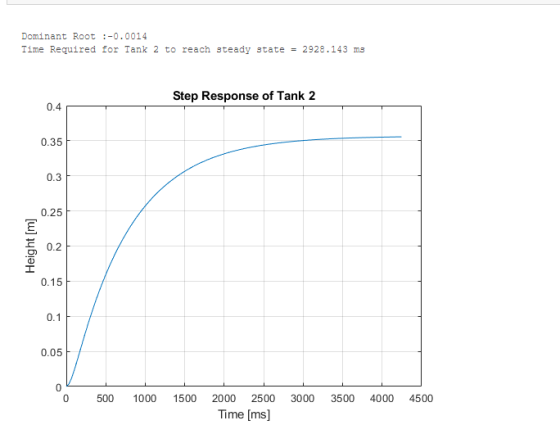
fprintf("\n Dominant Root :%.4f ",dominant_root);
S = stepinfo(H2); % Obtaining Step Info on H2(s)/Qmi(s)
ts = S.SettlingTime; % Getting Settling Time
fprintf("\n Time Required for Tank 2 to reach steady state = %.3f ms",ts);
% Simulating Step Response of H2(S)/Qmi(S)
opt = stepDataOptions('StepAmplitude',5); % Creating Step of amplitude 5
[H2,t] = step(H2,opt);
plot(t,H2)
xlabel("Time [ms]"); ylabel("Height [m]"); title("Step Response of Tank 2");
grid onAdd Answer to:
EGM 312: System Dynamics 5. Recall that the height deviation in the tanks of following system...
5 Consider the following air pneumatic system which is comprised of two rigid tanks of volume V a...
 5 Consider the following air pneumatic system which is comprised of two rigid tanks of volume V and V2. The variables δΡ-6p, and δΡ are small deviations around a reference steady-state pressure as The pneumatic lines have linearized resistances R1 and R Ci Py P2 a. Determine the pneumatic capacitances, Ci and Ca for the tanks undergoing an isothermal process at temperature T b. Derive a model of the pressures δΡυ and δΡ with δp, as the input. c.Define the...
For a Mechanical Engineering System Dynamics class 3. A system is modeled with the following equations....
 For a Mechanical Engineering System Dynamics class
3. A system is modeled with the following equations. * = y – 5x + d(t) y = 10f (t) – 30x The outputs are x(t) and y(t); the inputs are f(t) and d(t). a) b) c) From the two equations above, draw a complete block diagram for the model with X(s) at the rightmost position and F(s) at the leftmost position. All arrows must be shown clearly. Indicate the location of Y(s)...
For a Mechanical Engineering System Dynamics class
3. A system is modeled with the following equations. * = y – 5x + d(t) y = 10f (t) – 30x The outputs are x(t) and y(t); the inputs are f(t) and d(t). a) b) c) From the two equations above, draw a complete block diagram for the model with X(s) at the rightmost position and F(s) at the leftmost position. All arrows must be shown clearly. Indicate the location of Y(s)...
The state space model of an interconnected three tank water storage system is given by the following equation -3 1 o 1[hi] dt The heights of water in the tanks are, respectively, hi, h2, hz. Each tan...
 The state space model of an interconnected three tank water storage system is given by the following equation -3 1 o 1[hi] dt The heights of water in the tanks are, respectively, hi, h2, hz. Each tank has an independent input flow; the volume flow rates of input water into the three tanks are, respectively, qii,qi2, Oi3. Each tank also has a water discharge outlet and the volume flow rates of water coming out of the tanks are, respectively, qo1,...
The state space model of an interconnected three tank water storage system is given by the following equation: -3 1 0 1rh dt os lo 0 3] 10 1-3 The heights of water in the tanks are, respectively,...
 The state space model of an interconnected three tank water storage system is given by the following equation: -3 1 0 1rh dt os lo 0 3] 10 1-3 The heights of water in the tanks are, respectively, h,h2,h3. Each tank has an independent input flow; the volume flow rates of input water into the three tanks are, respectively, qǐ1,W2,4a. Each tank also has a water discharge outlet and the volume flow rates of water coming out of the tanks...
1. Consider a single tank for flow rate control and water level regulation. A single tank...
 1. Consider a single tank for flow rate control and water level regulation. A single tank subject to the pump dynamics can be modeled as follows Tank dynamics: h.-le,-4M h, -e-eyh.), Pump dynamics: Q,-1(av,-0) Pump dynamics: Q,--(av,-Q.) Tank dynamics: where the parameters are defined as follows: h :water level c: valve resistance r: time constant S,: water tank area Q,: supplied flow rate a: voltage scaling factor ,: applied control input voltage (all the coefficients are positive) (A). Please apply...
please do 1,2,3 Consider two tanks in series. Water flows into the first tank at a rate controlled by a control v...
 please do 1,2,3
Consider two tanks in series. Water flows into the first tank at a rate controlled by a control valve. The height of water in each tank is measured by a transducer at the bottom of the tank. The time constant for these transducers is 5 msec. These heights are sent to a Pl controller that outputs a voltage to the control valve. (You may assume the control ler simply outputs a flowrate.) The flowrate out of each...
please do 1,2,3
Consider two tanks in series. Water flows into the first tank at a rate controlled by a control valve. The height of water in each tank is measured by a transducer at the bottom of the tank. The time constant for these transducers is 5 msec. These heights are sent to a Pl controller that outputs a voltage to the control valve. (You may assume the control ler simply outputs a flowrate.) The flowrate out of each...
1. Consider a feedback system given below: T(s) Disturbance Controller Dynamics R(S) + Gc(s) G.(s) U(s)...
 1. Consider a feedback system given below: T(s) Disturbance Controller Dynamics R(S) + Gc(s) G.(s) U(s) Sensor H(s) IMs) Sensor noise where the input and transfer functions are given as follows: R(s) = –,7,(s) = 0, N(s) = 0, G, - 15,6, -_- , and H(s) = 1. s's + 3) a. Derive the system transfer function Y(s)/R(s) = G,, poles, $, On, and, from the response function y(t), the performance measures: rise time Tr, peak time Tp, percent overshoot...
Question A1 A single tank process has first order dynamics. When the inlet flow rate is...
 Question A1 A single tank process has first order dynamics. When the inlet flow rate is chosen as the input and the level as the output, the transfer function is as follows. 5 G(s) - H(s) 2. (S) S +1 91(t) h(t) *7 q:(0) q2(t) Fig. Q.Al schematic of the liquid level process (a) Determine the system constant t and steady state gain K. [6 marks] (b) For a unit step input q, (t) = 1(1), determine the time response...
For the following transfer function of an LTI system: Q.3) For the following transfer function of an ITI system: 8-5 (a...
 For the following transfer function of an LTI system:
Q.3) For the following transfer function of an ITI system: 8-5 (a) Sketch the pole-zero plot. (b) If the system is stable, determine the large Why. st pssible ROC. Is the systeu causal? Explairn (c) If the system is causal, determine the lar gest possible ROC. Is the system stable? Explain
Q.3) For the following transfer function of an ITI system: 8-5 (a) Sketch the pole-zero plot. (b) If the system...
For the following transfer function of an LTI system:
Q.3) For the following transfer function of an ITI system: 8-5 (a) Sketch the pole-zero plot. (b) If the system is stable, determine the large Why. st pssible ROC. Is the systeu causal? Explairn (c) If the system is causal, determine the lar gest possible ROC. Is the system stable? Explain
Q.3) For the following transfer function of an ITI system: 8-5 (a) Sketch the pole-zero plot. (b) If the system...
Consider the liquid level system shown in Figure 1. At steady state, the inflow rate and...
 Consider the liquid level system shown in Figure 1. At steady state, the inflow rate and outflow rate are both Ở and the flow rate between the tanks is zero. The heads at tank 1 and tank 2 are both H. At t = 0, the inflow rate is changed from 0 to + , where is the small change in the inflow rate. The resulting changes in the heads (h/ and h2) and flow rates are assumed to be...
 5 Consider the following air pneumatic system which is comprised of two rigid tanks of volume V and V2. The variables δΡ-6p, and δΡ are small deviations around a reference steady-state pressure as The pneumatic lines have linearized resistances R1 and R Ci Py P2 a. Determine the pneumatic capacitances, Ci and Ca for the tanks undergoing an isothermal process at temperature T b. Derive a model of the pressures δΡυ and δΡ with δp, as the input. c.Define the...
 For a Mechanical Engineering System Dynamics class
3. A system is modeled with the following equations. * = y – 5x + d(t) y = 10f (t) – 30x The outputs are x(t) and y(t); the inputs are f(t) and d(t). a) b) c) From the two equations above, draw a complete block diagram for the model with X(s) at the rightmost position and F(s) at the leftmost position. All arrows must be shown clearly. Indicate the location of Y(s)...
For a Mechanical Engineering System Dynamics class
3. A system is modeled with the following equations. * = y – 5x + d(t) y = 10f (t) – 30x The outputs are x(t) and y(t); the inputs are f(t) and d(t). a) b) c) From the two equations above, draw a complete block diagram for the model with X(s) at the rightmost position and F(s) at the leftmost position. All arrows must be shown clearly. Indicate the location of Y(s)...
 The state space model of an interconnected three tank water storage system is given by the following equation -3 1 o 1[hi] dt The heights of water in the tanks are, respectively, hi, h2, hz. Each tank has an independent input flow; the volume flow rates of input water into the three tanks are, respectively, qii,qi2, Oi3. Each tank also has a water discharge outlet and the volume flow rates of water coming out of the tanks are, respectively, qo1,...
 The state space model of an interconnected three tank water storage system is given by the following equation: -3 1 0 1rh dt os lo 0 3] 10 1-3 The heights of water in the tanks are, respectively, h,h2,h3. Each tank has an independent input flow; the volume flow rates of input water into the three tanks are, respectively, qǐ1,W2,4a. Each tank also has a water discharge outlet and the volume flow rates of water coming out of the tanks...
 1. Consider a single tank for flow rate control and water level regulation. A single tank subject to the pump dynamics can be modeled as follows Tank dynamics: h.-le,-4M h, -e-eyh.), Pump dynamics: Q,-1(av,-0) Pump dynamics: Q,--(av,-Q.) Tank dynamics: where the parameters are defined as follows: h :water level c: valve resistance r: time constant S,: water tank area Q,: supplied flow rate a: voltage scaling factor ,: applied control input voltage (all the coefficients are positive) (A). Please apply...
 please do 1,2,3
Consider two tanks in series. Water flows into the first tank at a rate controlled by a control valve. The height of water in each tank is measured by a transducer at the bottom of the tank. The time constant for these transducers is 5 msec. These heights are sent to a Pl controller that outputs a voltage to the control valve. (You may assume the control ler simply outputs a flowrate.) The flowrate out of each...
please do 1,2,3
Consider two tanks in series. Water flows into the first tank at a rate controlled by a control valve. The height of water in each tank is measured by a transducer at the bottom of the tank. The time constant for these transducers is 5 msec. These heights are sent to a Pl controller that outputs a voltage to the control valve. (You may assume the control ler simply outputs a flowrate.) The flowrate out of each...
 1. Consider a feedback system given below: T(s) Disturbance Controller Dynamics R(S) + Gc(s) G.(s) U(s) Sensor H(s) IMs) Sensor noise where the input and transfer functions are given as follows: R(s) = –,7,(s) = 0, N(s) = 0, G, - 15,6, -_- , and H(s) = 1. s's + 3) a. Derive the system transfer function Y(s)/R(s) = G,, poles, $, On, and, from the response function y(t), the performance measures: rise time Tr, peak time Tp, percent overshoot...
 Question A1 A single tank process has first order dynamics. When the inlet flow rate is chosen as the input and the level as the output, the transfer function is as follows. 5 G(s) - H(s) 2. (S) S +1 91(t) h(t) *7 q:(0) q2(t) Fig. Q.Al schematic of the liquid level process (a) Determine the system constant t and steady state gain K. [6 marks] (b) For a unit step input q, (t) = 1(1), determine the time response...
 For the following transfer function of an LTI system:
Q.3) For the following transfer function of an ITI system: 8-5 (a) Sketch the pole-zero plot. (b) If the system is stable, determine the large Why. st pssible ROC. Is the systeu causal? Explairn (c) If the system is causal, determine the lar gest possible ROC. Is the system stable? Explain
Q.3) For the following transfer function of an ITI system: 8-5 (a) Sketch the pole-zero plot. (b) If the system...
For the following transfer function of an LTI system:
Q.3) For the following transfer function of an ITI system: 8-5 (a) Sketch the pole-zero plot. (b) If the system is stable, determine the large Why. st pssible ROC. Is the systeu causal? Explairn (c) If the system is causal, determine the lar gest possible ROC. Is the system stable? Explain
Q.3) For the following transfer function of an ITI system: 8-5 (a) Sketch the pole-zero plot. (b) If the system...
 Consider the liquid level system shown in Figure 1. At steady state, the inflow rate and outflow rate are both Ở and the flow rate between the tanks is zero. The heads at tank 1 and tank 2 are both H. At t = 0, the inflow rate is changed from 0 to + , where is the small change in the inflow rate. The resulting changes in the heads (h/ and h2) and flow rates are assumed to be...
Most questions answered within 3 hours.
-
Write a program to score the paper-rock-scissor game. Each of
two users types in either P,R...
asked 7 minutes ago -
Calculate the equillibrium constent K for a redox reaction that
has E°cell = -.98 V at...
asked 19 minutes ago -
A concave spherical mirror has a radius of curvature of
magnitude 19.6 cm.
(a) Find the...
asked 21 minutes ago -
3. draw a diagram of the magnetic field:
a. around a long straight wire with a...
asked 19 minutes ago -
If you titrated 30.0 mL of 0.1 M HCl with 0.1 M NaOH, indicate
the approximate...
asked 28 minutes ago -
NADH passes electrons into the electron transport chain. List
the carriers that would receive the electrons,...
asked 36 minutes ago -
A cylindrical cable with a resistivity of 1.6x10⁻⁸ Ω·m and cross
sectional area of 3x10⁻⁵ m^2...
asked 36 minutes ago -
True or False.
A consumer with convex preferences who is indifferent between
the bundles (5,2) and...
asked 40 minutes ago -
A diamond's index of refraction for red light, 656 nm, is 2.410,
while that for blue...
asked 52 minutes ago -
Compare HPLC, SPE, and GC. Identify the differences, the
advantages, and the weaknesses of each method.
asked 54 minutes ago -
Characteristic x-rays emitted by potassium have a wavelength of
0.374 nm. What is the energy of...
asked 56 minutes ago -
there is a function to create two random numbers between 1 and
25 and a function...
asked 1 hour ago