
Homework Answers

Add Answer to:
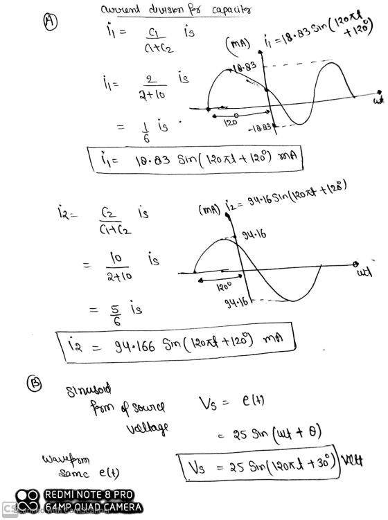
also draw the sinusoid forms
2) Consider the following network in Fig (2). If the voltage...
2. For the circuit of Fig. the source is sinusoid of 120 Vrms at a frequency...
 2. For the circuit of Fig. the source is sinusoid of 120 Vrms at a frequency of 60 Hz. The load resistor is 10 12. a) Draw the waveforms of source voltage, output voltage, output current, semiconductor device voltage and semiconductor device current. b) Calculate the average output voltage. c) Calculate the rms output voltage. d) Calculate the average output current. e) Calculate the power absorbed by the resistor. va + vs = Vm sin (@t) R Figure 1: Question...
2. Draw the output voltage waveform (mark axes with numerical values) of the following three- pha...
 2. Draw the output voltage waveform (mark axes with numerical values) of the following three- phase full-wave diode rectifier supplied from a balanced Y-connected ac source as shown in Fig. 1. The three input phase voltages are given in Fig. 2. Also calculate the de value of the output current if the load resistance is 5 2. Draw the line b current ib wave form. Secondary Fig. 1. Three-phase diode rectifier for problem 2 160 55.5 V an Vba 120...
1. A star connected secondary of a 60 Hz 3-phase transformer, as shown in Fig. 3, is supplying a ...
 1. A star connected secondary of a 60 Hz 3-phase transformer, as shown in Fig. 3, is supplying a 3-phase HW uncontrolled rectifier loaded with a pure 10 Ω resistor. The fuse Fy is open circuit. L. Determine the conduction periods of the diodes ii Draw the waveform of the output voltage. F1 D D and D in msec. phase A iii. Calculate the secondary line voltage if the average iv. Draw the waveforms of the supply currents i, and...
4. The half-wave rectifier in Fig. P3.94 is operating with an input voltage, V = 10...
 4. The half-wave rectifier in Fig. P3.94 is operating with an input voltage, V = 10 sinat,at a frequency of 60 Hz and Von=1V. (25 points) C D Les = Figure P3.94 a. Draw the output voltage (Vo(t)) waveform. b. What is the minimum value of C required to maintain the ripple voltage to less than 0.25V if R=0.5 Q and the diode voltage drop is 1V? c. What is the PIV rating of the diode in this circuit? d....
Problem 3 Find the output voltage (vo) for the following network where the input voltage is...
 Problem 3 Find the output voltage (vo) for the following network where the input voltage is the one shown on the left hand side of Fig. 3. Explain your answer in detail and you can assume that the circuit has an ideal diode. C = 1 uF AV f = 1000 Hz 9 + + R 100 ks2 V V = 5V 2019 -20 -- PL Fig. 3
(3.)(25 points) Consider the following electric power network illustrated in Fig. ure 1 below. 392 1992...
 (3.)(25 points) Consider the following electric power network illustrated in Fig. ure 1 below. 392 1992 6+ LINE V LINE LOAD LOAD 16 Figure 1 VR = 5.020 kV Vs = 5.0250kV Answer the following questions. (a.) Find ILOAD (b.) What is the power factor of the load? (c.) What is the complex power of the load? (d.) What is the complex power of the line? (e.) What is the complex power seen at the sending-end of the line? (f.)...
Consider the impedance diagram of a simple energy distribution network seen in fig. 1. The transmission...
 Consider the impedance diagram of a simple energy distribution network seen in fig. 1. The transmission lines that connect the buses have the line impedances as shown in the figure. The generators connected to buses 1 and 2 are known to be E1=1.0 pu (per unit) and E2=0.5 pu, respectively, on a 1 MV base. a) (05) Draw the admittance diagram for the system shown in fig. 1. b) (10) Obtain the bus admittance matrix Ybus for the system. c)...
Consider the one-port AC network below. Given the following values: C1 = 46 microfarads R2 =...
 Consider the one-port AC network below. Given the following values: C1 = 46 microfarads R2 = 40 ohms Voltage source = olts at 50 Hz. What is the magnitude of the Thevenin Equivalent phasor voltage in volts? to 110 Frequency, f= 50 Hz Consider the one-port AC network below. Given the following values: C1 = 49 microfarads R2 = 82 ohms Voltage source = 10 e jo volts at 50 Hz. What is the phase of the Thevenin Equivalent phasor...
Question 2 (10%) The input to the circuit shown in Fig. 2 is the voltage source...
 Question 2 (10%) The input to the circuit shown in Fig. 2 is the voltage source vs(t). The output is the voltage across two open terminals, vo(). If v()-3-(t) V, the output is the voltage vo()-10+Se30* V for 20. Determine the values of Ri and R2. 2 sa) olt) Fig. 2
10. Two loads connected in parallel draw a total of 2.4 kW at 0.8 pflagging from...
 10. Two loads connected in parallel draw a total of 2.4 kW at 0.8 pflagging from a 120-V rms, 60- Hz line. One load absorbs 1.5 kW at a 0.707 pf lagging. Determine: (a) the pf of the second load, INV 11. Calculate the line currents for the system shown in figure. Calculate also the total power and reactive power consumed by the load. w 12. For the balanced three-phase circuit in Fig.. Calculate the line currents, the phase voltage...
 2. For the circuit of Fig. the source is sinusoid of 120 Vrms at a frequency of 60 Hz. The load resistor is 10 12. a) Draw the waveforms of source voltage, output voltage, output current, semiconductor device voltage and semiconductor device current. b) Calculate the average output voltage. c) Calculate the rms output voltage. d) Calculate the average output current. e) Calculate the power absorbed by the resistor. va + vs = Vm sin (@t) R Figure 1: Question...
 2. Draw the output voltage waveform (mark axes with numerical values) of the following three- phase full-wave diode rectifier supplied from a balanced Y-connected ac source as shown in Fig. 1. The three input phase voltages are given in Fig. 2. Also calculate the de value of the output current if the load resistance is 5 2. Draw the line b current ib wave form. Secondary Fig. 1. Three-phase diode rectifier for problem 2 160 55.5 V an Vba 120...
 1. A star connected secondary of a 60 Hz 3-phase transformer, as shown in Fig. 3, is supplying a 3-phase HW uncontrolled rectifier loaded with a pure 10 Ω resistor. The fuse Fy is open circuit. L. Determine the conduction periods of the diodes ii Draw the waveform of the output voltage. F1 D D and D in msec. phase A iii. Calculate the secondary line voltage if the average iv. Draw the waveforms of the supply currents i, and...
 4. The half-wave rectifier in Fig. P3.94 is operating with an input voltage, V = 10 sinat,at a frequency of 60 Hz and Von=1V. (25 points) C D Les = Figure P3.94 a. Draw the output voltage (Vo(t)) waveform. b. What is the minimum value of C required to maintain the ripple voltage to less than 0.25V if R=0.5 Q and the diode voltage drop is 1V? c. What is the PIV rating of the diode in this circuit? d....
 Problem 3 Find the output voltage (vo) for the following network where the input voltage is the one shown on the left hand side of Fig. 3. Explain your answer in detail and you can assume that the circuit has an ideal diode. C = 1 uF AV f = 1000 Hz 9 + + R 100 ks2 V V = 5V 2019 -20 -- PL Fig. 3
 (3.)(25 points) Consider the following electric power network illustrated in Fig. ure 1 below. 392 1992 6+ LINE V LINE LOAD LOAD 16 Figure 1 VR = 5.020 kV Vs = 5.0250kV Answer the following questions. (a.) Find ILOAD (b.) What is the power factor of the load? (c.) What is the complex power of the load? (d.) What is the complex power of the line? (e.) What is the complex power seen at the sending-end of the line? (f.)...
 Consider the impedance diagram of a simple energy distribution network seen in fig. 1. The transmission lines that connect the buses have the line impedances as shown in the figure. The generators connected to buses 1 and 2 are known to be E1=1.0 pu (per unit) and E2=0.5 pu, respectively, on a 1 MV base. a) (05) Draw the admittance diagram for the system shown in fig. 1. b) (10) Obtain the bus admittance matrix Ybus for the system. c)...
 Consider the one-port AC network below. Given the following values: C1 = 46 microfarads R2 = 40 ohms Voltage source = olts at 50 Hz. What is the magnitude of the Thevenin Equivalent phasor voltage in volts? to 110 Frequency, f= 50 Hz Consider the one-port AC network below. Given the following values: C1 = 49 microfarads R2 = 82 ohms Voltage source = 10 e jo volts at 50 Hz. What is the phase of the Thevenin Equivalent phasor...
 Question 2 (10%) The input to the circuit shown in Fig. 2 is the voltage source vs(t). The output is the voltage across two open terminals, vo(). If v()-3-(t) V, the output is the voltage vo()-10+Se30* V for 20. Determine the values of Ri and R2. 2 sa) olt) Fig. 2
 10. Two loads connected in parallel draw a total of 2.4 kW at 0.8 pflagging from a 120-V rms, 60- Hz line. One load absorbs 1.5 kW at a 0.707 pf lagging. Determine: (a) the pf of the second load, INV 11. Calculate the line currents for the system shown in figure. Calculate also the total power and reactive power consumed by the load. w 12. For the balanced three-phase circuit in Fig.. Calculate the line currents, the phase voltage...
Most questions answered within 3 hours.
-
When two wires of identical dimensions are used to hang 25.0 kg
weights, wire A is...
asked 10 minutes ago -
Implement a program (in both C# and Python) which includes a
user-defined exception giving a message...
asked 15 minutes ago -
If an ocean wave passes a stationary point every 4 s and has a
velocity of...
asked 22 minutes ago -
A train consists of a 4300-kg locomotive pulling two loaded
boxcars. The first boxcar has a...
asked 28 minutes ago -
The four 1.04g spheres shown below have q+ve = 12.0nC
and d=2.81cm. The spheres are released...
asked 29 minutes ago -
Give the identity of the unknown group 1 metal/chloride salt with
molar mass 285.75 g/mol
asked 33 minutes ago -
how
to balance this equation?
MnO2
+ PbO2
+ HNO3
→ HMnO4
+ Pb(NO3)2
+ H2O...
asked 40 minutes ago -
Most of the Central Banks including the Bank of Canada
cutting their benchmark interest rates, please...
asked 43 minutes ago -
A force of at least 1900N (Newtons) is required to initially
push a large object from...
asked 56 minutes ago -
Max Welte has converted an industrial bond to cash and is now
considering other investment opportunities...
asked 1 hour ago -
A plated distillation column is designed to produce 8000 kg h-1
distillate and 15000 kg h-1...
asked 56 minutes ago -
please write your own word, don't copy type and answer all of
them then I will...
asked 59 minutes ago