
Homework Answers

Add Answer to:
1. A star connected secondary of a 60 Hz 3-phase transformer, as shown in Fig. 3, is supplying a ...
1. A 50 Hz 3-phase Have wave uncontrolled rectifier circuit is used to supply a resistive load of...
 1. A 50 Hz 3-phase Have wave uncontrolled rectifier circuit is used to supply a resistive load of 100 ohms. The supply is unbalanced and defined as v.-127.28 cos (ot) V 127.28 sin (ot-0.5236) V n63.64 cos (ot+2.0944) V a) Draw the circuit diagram. b) Draw the three phase voltages wave forms. c) Use phasor diagram or any other method to obtain the line voltages v and d) Draw the line voltages v and v wave forms. e) Derive an...
1- A three-pulse uncontrolled rectifier is connected to a 3 phase, 4 wire , 220 V...
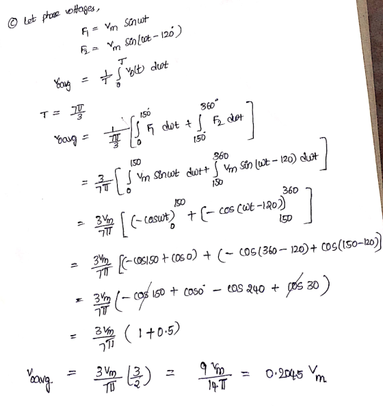
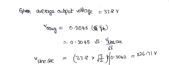
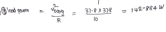
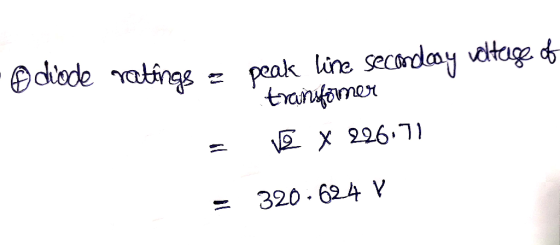
 1- A three-pulse uncontrolled rectifier is connected to a 3 phase, 4 wire , 220 V , 60 Hz source. If the load is resistive load R 20 2, Find: The maximum load voltage and current а- b- The average load voltage ,load current, and diode current The voltage and current rating of the diode с- Draw the waveforms of output voltage, output current, diodes current, d- and diodes voltage.
A 3-j semi-controlled bridge rectifier is fed from a delta-star transformer 66 kVA, 60 Hz, 13800 ...
A 3-j semi-controlled bridge rectifier is fed from a delta-star transformer 66 kVA, 60 Hz, 13800 V/? (the secondary voltage is unknown). The load of the rectifier is highly inductive. The following measurements at a specified firing angle have been recorded: Ith RMS 70.71 A I line RMS (transformer secondary) 76.40 A Draw the complete circuit diagram and calculate; i. Load current Io. ii. Firing angle α. iii. Transformer secondary line voltage (RMS). iiii. Average output voltage (at the calculated...
A 3-j semi-controlled bridge rectifier is fed from a delta-star transformer 66 kVA, 60 Hz, 13800...
A 3-j semi-controlled bridge rectifier is fed from a delta-star transformer 66 kVA, 60 Hz, 13800 V/? (the secondary voltage is unknown). The load of the rectifier is highly inductive. The following measurements at a specified firing angle have been recorded: Ith RMS 70.71 A I line RMS (transformer secondary) 76.40 A Draw the complete circuit diagram and calculate; i. Load current Io. ii. Firing angle α. iii. Transformer secondary line voltage (RMS). iiii. Average output voltage (at the calculated...
1. (10 PT) A three-phase bridge rectifier circuit shown in the figure phase voltage of 220 volts rms. A load of 100 Ω is connected across is supplied by a rectifier. Both the primary and secondary...
 1. (10 PT) A three-phase bridge rectifier circuit shown in the figure phase voltage of 220 volts rms. A load of 100 Ω is connected across is supplied by a rectifier. Both the primary and secondary windings of transfor Assume the transformer has a turns ratio of unity mer are Y-connected a) 3 PTI On the top of voltage plot on next page indicate the diodes that will be conducting during different intervals of time. b) 17 PT] Plot the...
i want the answer with detales Single-Phase Controlled Rectifier Exercise Derive the expressions of the average...
 i want the answer with detales
Single-Phase Controlled Rectifier Exercise Derive the expressions of the average load voltage and current in single-phase half-wave controlled rectifiers and resistive load. Draw the waveforms of supply voltage. output voltage, output current, thyristor voltage and thyristor current Exercise In a single-phase half-wave controlled rectifier and resistive kad, it is desired to get an average load voltage of 80 V. Determine the firing angle if the ac supply voltage is 230 V. If the load...
i want the answer with detales
Single-Phase Controlled Rectifier Exercise Derive the expressions of the average load voltage and current in single-phase half-wave controlled rectifiers and resistive load. Draw the waveforms of supply voltage. output voltage, output current, thyristor voltage and thyristor current Exercise In a single-phase half-wave controlled rectifier and resistive kad, it is desired to get an average load voltage of 80 V. Determine the firing angle if the ac supply voltage is 230 V. If the load...
Design a FULL WAVE BRIDGE RECTIFIER circuit that will: Take 120volts ac, 60 hz, sinusoidal waveform...
 Design a FULL WAVE BRIDGE RECTIFIER circuit that will:
Take 120volts ac, 60 hz, sinusoidal waveform and convert
it to a “regulated “dc value
giving 12 volts +, - 1 volt across a 2000-ohm output
load resistor with no more than 2%
ripple voltage.
You may assume:
a. An ideal power transformer as discussed in class.
b. For hand computations, you must assume a diode given by
Figure 4.8 page 185.
c. A filter capacitor sized per the textbook equation...
Design a FULL WAVE BRIDGE RECTIFIER circuit that will:
Take 120volts ac, 60 hz, sinusoidal waveform and convert
it to a “regulated “dc value
giving 12 volts +, - 1 volt across a 2000-ohm output
load resistor with no more than 2%
ripple voltage.
You may assume:
a. An ideal power transformer as discussed in class.
b. For hand computations, you must assume a diode given by
Figure 4.8 page 185.
c. A filter capacitor sized per the textbook equation...
Even just steps/formula on what to follow would be sufficient if you cannot complete the question.
 Even just steps/formula on what to follow would be sufficient if
you cannot complete the question.
Draw a bridge rectifier fed from a single-phase 240-V (Au) supply with a 4:1 step down transformer. A 10-2 load is connected to the output. Assume a simplified model for the diodes with VoN 1V per diode and zero leakage current. (a) Draw voltage, current and p(t) waveforms for one diode. (b) Derive the diode voltage spec from the voltage waveforms, and add 50%...
Even just steps/formula on what to follow would be sufficient if
you cannot complete the question.
Draw a bridge rectifier fed from a single-phase 240-V (Au) supply with a 4:1 step down transformer. A 10-2 load is connected to the output. Assume a simplified model for the diodes with VoN 1V per diode and zero leakage current. (a) Draw voltage, current and p(t) waveforms for one diode. (b) Derive the diode voltage spec from the voltage waveforms, and add 50%...
In this part of the term paper, design a single-phase switch-mode DC power supply with a forward ...
 In this part of the term paper, design a single-phase switch-mode DC power supply with a forward converter. Provide answers to the questions below Please combine the single-phase full-wave rectifier from part two of your term paper with a forward converter to produce a switch-mode DC power supply, as shown below. The output of the bridge rectifier serves as input to the forward converter L1 Np: N BH621BH62 D, V1 Load C1 100p 45 Vrms D3 BH62 18H62 D4 Control...
1) A classical rectifier uses a standard 120 V/25.2 V 60 Hz transformer. What ideal output...
 1) A classical rectifier uses a standard 120 V/25.2 V 60 Hz transformer. What ideal output DC voltage will result if a single-phase full-wave diode bridge is used with a large capacitor and the input is exactly 120 Vrms? Assume each diode's forward voltage drop is 1 V. Design a capacitor if the load is 50 W and the voltage ripple is 1 V peak-peak?
 1. A 50 Hz 3-phase Have wave uncontrolled rectifier circuit is used to supply a resistive load of 100 ohms. The supply is unbalanced and defined as v.-127.28 cos (ot) V 127.28 sin (ot-0.5236) V n63.64 cos (ot+2.0944) V a) Draw the circuit diagram. b) Draw the three phase voltages wave forms. c) Use phasor diagram or any other method to obtain the line voltages v and d) Draw the line voltages v and v wave forms. e) Derive an...
 1- A three-pulse uncontrolled rectifier is connected to a 3 phase, 4 wire , 220 V , 60 Hz source. If the load is resistive load R 20 2, Find: The maximum load voltage and current а- b- The average load voltage ,load current, and diode current The voltage and current rating of the diode с- Draw the waveforms of output voltage, output current, diodes current, d- and diodes voltage.
 1. (10 PT) A three-phase bridge rectifier circuit shown in the figure phase voltage of 220 volts rms. A load of 100 Ω is connected across is supplied by a rectifier. Both the primary and secondary windings of transfor Assume the transformer has a turns ratio of unity mer are Y-connected a) 3 PTI On the top of voltage plot on next page indicate the diodes that will be conducting during different intervals of time. b) 17 PT] Plot the...
 i want the answer with detales
Single-Phase Controlled Rectifier Exercise Derive the expressions of the average load voltage and current in single-phase half-wave controlled rectifiers and resistive load. Draw the waveforms of supply voltage. output voltage, output current, thyristor voltage and thyristor current Exercise In a single-phase half-wave controlled rectifier and resistive kad, it is desired to get an average load voltage of 80 V. Determine the firing angle if the ac supply voltage is 230 V. If the load...
i want the answer with detales
Single-Phase Controlled Rectifier Exercise Derive the expressions of the average load voltage and current in single-phase half-wave controlled rectifiers and resistive load. Draw the waveforms of supply voltage. output voltage, output current, thyristor voltage and thyristor current Exercise In a single-phase half-wave controlled rectifier and resistive kad, it is desired to get an average load voltage of 80 V. Determine the firing angle if the ac supply voltage is 230 V. If the load...
 Design a FULL WAVE BRIDGE RECTIFIER circuit that will:
Take 120volts ac, 60 hz, sinusoidal waveform and convert
it to a “regulated “dc value
giving 12 volts +, - 1 volt across a 2000-ohm output
load resistor with no more than 2%
ripple voltage.
You may assume:
a. An ideal power transformer as discussed in class.
b. For hand computations, you must assume a diode given by
Figure 4.8 page 185.
c. A filter capacitor sized per the textbook equation...
Design a FULL WAVE BRIDGE RECTIFIER circuit that will:
Take 120volts ac, 60 hz, sinusoidal waveform and convert
it to a “regulated “dc value
giving 12 volts +, - 1 volt across a 2000-ohm output
load resistor with no more than 2%
ripple voltage.
You may assume:
a. An ideal power transformer as discussed in class.
b. For hand computations, you must assume a diode given by
Figure 4.8 page 185.
c. A filter capacitor sized per the textbook equation...
 Even just steps/formula on what to follow would be sufficient if
you cannot complete the question.
Draw a bridge rectifier fed from a single-phase 240-V (Au) supply with a 4:1 step down transformer. A 10-2 load is connected to the output. Assume a simplified model for the diodes with VoN 1V per diode and zero leakage current. (a) Draw voltage, current and p(t) waveforms for one diode. (b) Derive the diode voltage spec from the voltage waveforms, and add 50%...
Even just steps/formula on what to follow would be sufficient if
you cannot complete the question.
Draw a bridge rectifier fed from a single-phase 240-V (Au) supply with a 4:1 step down transformer. A 10-2 load is connected to the output. Assume a simplified model for the diodes with VoN 1V per diode and zero leakage current. (a) Draw voltage, current and p(t) waveforms for one diode. (b) Derive the diode voltage spec from the voltage waveforms, and add 50%...
 In this part of the term paper, design a single-phase switch-mode DC power supply with a forward converter. Provide answers to the questions below Please combine the single-phase full-wave rectifier from part two of your term paper with a forward converter to produce a switch-mode DC power supply, as shown below. The output of the bridge rectifier serves as input to the forward converter L1 Np: N BH621BH62 D, V1 Load C1 100p 45 Vrms D3 BH62 18H62 D4 Control...
 1) A classical rectifier uses a standard 120 V/25.2 V 60 Hz transformer. What ideal output DC voltage will result if a single-phase full-wave diode bridge is used with a large capacitor and the input is exactly 120 Vrms? Assume each diode's forward voltage drop is 1 V. Design a capacitor if the load is 50 W and the voltage ripple is 1 V peak-peak?
Most questions answered within 3 hours.
-
A 8.15- g bullet from a 9-mm pistol has a velocity of 366.0 m/s.
It strikes...
asked 1 hour ago -
The outstanding bonds of Alpha Extracts have a yield to maturity
of 7.4 percent and a...
asked 1 hour ago -
The Problem: The Case of the Harmonizing Vacations
Your CEO is exploring partnering with a European...
asked 2 hours ago -
A chemical equation is balanced by adding coefficients in front
of some formulas so that the...
asked 2 hours ago -
From the literature (reference your sources): What are the
lattice parameters of calcite and aragonite? Why...
asked 3 hours ago -
Your system is rejecting the question am asking which is
preceded by a case study. It...
asked 3 hours ago -
3. On January 2, 2000, Larry creates a trust with himself as
trustee. Larry as trustee...
asked 3 hours ago -
A member of the volleyball team spikes the ball. During this
process, she changes the velocity...
asked 3 hours ago -
Are adult gamers less likely to use a gaming console (Xbox,
PlayStation, Wii, etc...) than teen...
asked 4 hours ago -
The University of
Texas recently reported that 43% of college students aged 18-24
would spend their...
asked 4 hours ago -
The length of stay at a specific emergency department in
Phoenix, Arizona, in 2009 had a...
asked 3 hours ago -
. Please give the mechanism for this type of problem. Step by
Step
The toxin that...
asked 3 hours ago