
Homework Answers


Add Answer to:
1- A three-pulse uncontrolled rectifier is connected to a 3 phase, 4 wire , 220 V...
1. A 50 Hz 3-phase Have wave uncontrolled rectifier circuit is used to supply a resistive load of...
 1. A 50 Hz 3-phase Have wave uncontrolled rectifier circuit is used to supply a resistive load of 100 ohms. The supply is unbalanced and defined as v.-127.28 cos (ot) V 127.28 sin (ot-0.5236) V n63.64 cos (ot+2.0944) V a) Draw the circuit diagram. b) Draw the three phase voltages wave forms. c) Use phasor diagram or any other method to obtain the line voltages v and d) Draw the line voltages v and v wave forms. e) Derive an...
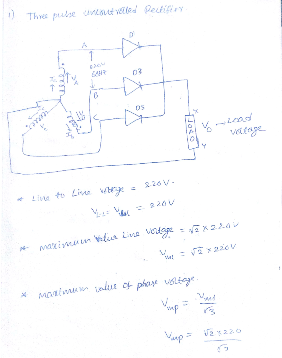
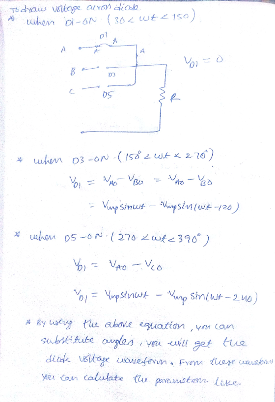
1. A star connected secondary of a 60 Hz 3-phase transformer, as shown in Fig. 3, is supplying a ...
 1. A star connected secondary of a 60 Hz 3-phase transformer, as shown in Fig. 3, is supplying a 3-phase HW uncontrolled rectifier loaded with a pure 10 Ω resistor. The fuse Fy is open circuit. L. Determine the conduction periods of the diodes ii Draw the waveform of the output voltage. F1 D D and D in msec. phase A iii. Calculate the secondary line voltage if the average iv. Draw the waveforms of the supply currents i, and...
i want the answer with detales Single-Phase Controlled Rectifier Exercise Derive the expressions of the average...
 i want the answer with detales
Single-Phase Controlled Rectifier Exercise Derive the expressions of the average load voltage and current in single-phase half-wave controlled rectifiers and resistive load. Draw the waveforms of supply voltage. output voltage, output current, thyristor voltage and thyristor current Exercise In a single-phase half-wave controlled rectifier and resistive kad, it is desired to get an average load voltage of 80 V. Determine the firing angle if the ac supply voltage is 230 V. If the load...
i want the answer with detales
Single-Phase Controlled Rectifier Exercise Derive the expressions of the average load voltage and current in single-phase half-wave controlled rectifiers and resistive load. Draw the waveforms of supply voltage. output voltage, output current, thyristor voltage and thyristor current Exercise In a single-phase half-wave controlled rectifier and resistive kad, it is desired to get an average load voltage of 80 V. Determine the firing angle if the ac supply voltage is 230 V. If the load...
1. (10 PT) A three-phase bridge rectifier circuit shown in the figure phase voltage of 220 volts rms. A load of 100 Ω is connected across is supplied by a rectifier. Both the primary and secondary...
 1. (10 PT) A three-phase bridge rectifier circuit shown in the figure phase voltage of 220 volts rms. A load of 100 Ω is connected across is supplied by a rectifier. Both the primary and secondary windings of transfor Assume the transformer has a turns ratio of unity mer are Y-connected a) 3 PTI On the top of voltage plot on next page indicate the diodes that will be conducting during different intervals of time. b) 17 PT] Plot the...
Need help with e) and f). e) Derive a formula and give the numerical value for the input power factor of Phase A. f) Derive a formula and give the numerical value for the THD of the line current ia(...
 Need help with e) and f).
e) Derive a formula and give the numerical value for the input
power factor of Phase A.
f) Derive a formula and give the numerical value for the THD
of the line current ia(t)
Q3: Three-phase rectifier with six diodes [15pts] The three-phase diode-rectifier below has six diodes and a purely resistive load Rout. The sinusoidal input voltage sources (with a phase difference of 120') are star-connected and have the line-to- neutral amplitude Vn...
Need help with e) and f).
e) Derive a formula and give the numerical value for the input
power factor of Phase A.
f) Derive a formula and give the numerical value for the THD
of the line current ia(t)
Q3: Three-phase rectifier with six diodes [15pts] The three-phase diode-rectifier below has six diodes and a purely resistive load Rout. The sinusoidal input voltage sources (with a phase difference of 120') are star-connected and have the line-to- neutral amplitude Vn...
can you calculate and explain why? thanks A single-phase thyristor rectifier as 50 Hz source. The...
 can you calculate and explain why? thanks
A single-phase thyristor rectifier as 50 Hz source. The rectifier delivers a DC voltage of 150 V to a highly inductive depicted in Figure 1 is fed from a 220 V rms, 1. load with a resistive value of 10 Q. SCR, T SCR2 + is Vo SCR3 SCR T Figure 1 (a) for a delay angle component indicating its phase shift with respect to the input voltage v, Sketch the net rectifier...
can you calculate and explain why? thanks
A single-phase thyristor rectifier as 50 Hz source. The rectifier delivers a DC voltage of 150 V to a highly inductive depicted in Figure 1 is fed from a 220 V rms, 1. load with a resistive value of 10 Q. SCR, T SCR2 + is Vo SCR3 SCR T Figure 1 (a) for a delay angle component indicating its phase shift with respect to the input voltage v, Sketch the net rectifier...
D *4.80 It is required to use a peak rectifier to design a de power supply...
 D *4.80 It is required to use a peak rectifier to design a de power supply that provides an average de output voltage of 12 V on which a maximum of ±1-V ripple is allowed. The rectifier feeds a load of 200 2. The rectifier is fed from the line voltage (120 V rms, 60 Hz) through a transformer. The diodes available have 0.7-V drop when conducting. If the designer opts for the half-wave circuit: (a) Specify the rms voltage...
Controlled three-phase rectifiers Figure 4-20a shows a controlled six-pulse three-phase rectifier. The delay angle a is...
 Controlled three-phase rectifiers Figure 4-20a shows a controlled six-pulse three-phase rectifier. The delay angle a is referenced from where the SCR would begin to conduct if it were a diode. Sketch the output voltage of the controlled rectifier for a delay angle of 60°
1. A full-bridge three-phase SCR rectifier supplies an L-R load from a 208 V line-to-line 60...
 1. A full-bridge three-phase SCR rectifier supplies an L-R load from a 208 V line-to-line 60 Hz source. The load draws 25 kW when the SCR phase delay angle is 60°. What is the pulse number for this rectifier circuit? Plot the load power as a function of delay angle for 0° < α 75°
D Question 2 10 pts A three phase full-bridge rectifier draws 12-kW from a power supply that has 150-V phase-to-phase voltage. The power factor is 0.77. What is the maximum (peak) value of the cur...
 D Question 2 10 pts A three phase full-bridge rectifier draws 12-kW from a power supply that has 150-V phase-to-phase voltage. The power factor is 0.77. What is the maximum (peak) value of the current delivered by the supply? 10 pts DI Question 3 A full bridge, square wave inverter supplies an RL load with R-7-Ohm and L-58-mH. The DC voltage is 90-V and the output waveform frequency is 60-Hz. What is the magnitude of the third harmonic of the...
 1. A 50 Hz 3-phase Have wave uncontrolled rectifier circuit is used to supply a resistive load of 100 ohms. The supply is unbalanced and defined as v.-127.28 cos (ot) V 127.28 sin (ot-0.5236) V n63.64 cos (ot+2.0944) V a) Draw the circuit diagram. b) Draw the three phase voltages wave forms. c) Use phasor diagram or any other method to obtain the line voltages v and d) Draw the line voltages v and v wave forms. e) Derive an...
 1. A star connected secondary of a 60 Hz 3-phase transformer, as shown in Fig. 3, is supplying a 3-phase HW uncontrolled rectifier loaded with a pure 10 Ω resistor. The fuse Fy is open circuit. L. Determine the conduction periods of the diodes ii Draw the waveform of the output voltage. F1 D D and D in msec. phase A iii. Calculate the secondary line voltage if the average iv. Draw the waveforms of the supply currents i, and...
 i want the answer with detales
Single-Phase Controlled Rectifier Exercise Derive the expressions of the average load voltage and current in single-phase half-wave controlled rectifiers and resistive load. Draw the waveforms of supply voltage. output voltage, output current, thyristor voltage and thyristor current Exercise In a single-phase half-wave controlled rectifier and resistive kad, it is desired to get an average load voltage of 80 V. Determine the firing angle if the ac supply voltage is 230 V. If the load...
i want the answer with detales
Single-Phase Controlled Rectifier Exercise Derive the expressions of the average load voltage and current in single-phase half-wave controlled rectifiers and resistive load. Draw the waveforms of supply voltage. output voltage, output current, thyristor voltage and thyristor current Exercise In a single-phase half-wave controlled rectifier and resistive kad, it is desired to get an average load voltage of 80 V. Determine the firing angle if the ac supply voltage is 230 V. If the load...
 1. (10 PT) A three-phase bridge rectifier circuit shown in the figure phase voltage of 220 volts rms. A load of 100 Ω is connected across is supplied by a rectifier. Both the primary and secondary windings of transfor Assume the transformer has a turns ratio of unity mer are Y-connected a) 3 PTI On the top of voltage plot on next page indicate the diodes that will be conducting during different intervals of time. b) 17 PT] Plot the...
 Need help with e) and f).
e) Derive a formula and give the numerical value for the input
power factor of Phase A.
f) Derive a formula and give the numerical value for the THD
of the line current ia(t)
Q3: Three-phase rectifier with six diodes [15pts] The three-phase diode-rectifier below has six diodes and a purely resistive load Rout. The sinusoidal input voltage sources (with a phase difference of 120') are star-connected and have the line-to- neutral amplitude Vn...
Need help with e) and f).
e) Derive a formula and give the numerical value for the input
power factor of Phase A.
f) Derive a formula and give the numerical value for the THD
of the line current ia(t)
Q3: Three-phase rectifier with six diodes [15pts] The three-phase diode-rectifier below has six diodes and a purely resistive load Rout. The sinusoidal input voltage sources (with a phase difference of 120') are star-connected and have the line-to- neutral amplitude Vn...
 can you calculate and explain why? thanks
A single-phase thyristor rectifier as 50 Hz source. The rectifier delivers a DC voltage of 150 V to a highly inductive depicted in Figure 1 is fed from a 220 V rms, 1. load with a resistive value of 10 Q. SCR, T SCR2 + is Vo SCR3 SCR T Figure 1 (a) for a delay angle component indicating its phase shift with respect to the input voltage v, Sketch the net rectifier...
can you calculate and explain why? thanks
A single-phase thyristor rectifier as 50 Hz source. The rectifier delivers a DC voltage of 150 V to a highly inductive depicted in Figure 1 is fed from a 220 V rms, 1. load with a resistive value of 10 Q. SCR, T SCR2 + is Vo SCR3 SCR T Figure 1 (a) for a delay angle component indicating its phase shift with respect to the input voltage v, Sketch the net rectifier...
 D *4.80 It is required to use a peak rectifier to design a de power supply that provides an average de output voltage of 12 V on which a maximum of ±1-V ripple is allowed. The rectifier feeds a load of 200 2. The rectifier is fed from the line voltage (120 V rms, 60 Hz) through a transformer. The diodes available have 0.7-V drop when conducting. If the designer opts for the half-wave circuit: (a) Specify the rms voltage...
 Controlled three-phase rectifiers Figure 4-20a shows a controlled six-pulse three-phase rectifier. The delay angle a is referenced from where the SCR would begin to conduct if it were a diode. Sketch the output voltage of the controlled rectifier for a delay angle of 60°
 1. A full-bridge three-phase SCR rectifier supplies an L-R load from a 208 V line-to-line 60 Hz source. The load draws 25 kW when the SCR phase delay angle is 60°. What is the pulse number for this rectifier circuit? Plot the load power as a function of delay angle for 0° < α 75°
 D Question 2 10 pts A three phase full-bridge rectifier draws 12-kW from a power supply that has 150-V phase-to-phase voltage. The power factor is 0.77. What is the maximum (peak) value of the current delivered by the supply? 10 pts DI Question 3 A full bridge, square wave inverter supplies an RL load with R-7-Ohm and L-58-mH. The DC voltage is 90-V and the output waveform frequency is 60-Hz. What is the magnitude of the third harmonic of the...
Most questions answered within 3 hours.
-
You have a 825.3 mL sample of 2.754 M HA (Ka =
4.49⋅10−4). Calculate the pH...
asked 11 minutes ago -
The blues made its way into many kinds of music. Eric Clapton,
The Beatles, and Elvis...
asked 2 hours ago -
8. A wave in a string has a wave function given by: y (x, t) =...
asked 1 hour ago -
If you’re standing at the bottom of a hill and asked to evaluate
it while being...
asked 3 hours ago -
1. Which region has taken the lead in the world of
e-waste handling?
a) European Union...
asked 3 hours ago -
A 8.15- g bullet from a 9-mm pistol has a velocity of 366.0 m/s.
It strikes...
asked 4 hours ago -
The outstanding bonds of Alpha Extracts have a yield to maturity
of 7.4 percent and a...
asked 4 hours ago -
The Problem: The Case of the Harmonizing Vacations
Your CEO is exploring partnering with a European...
asked 5 hours ago -
A chemical equation is balanced by adding coefficients in front
of some formulas so that the...
asked 5 hours ago -
From the literature (reference your sources): What are the
lattice parameters of calcite and aragonite? Why...
asked 6 hours ago -
Your system is rejecting the question am asking which is
preceded by a case study. It...
asked 6 hours ago -
3. On January 2, 2000, Larry creates a trust with himself as
trustee. Larry as trustee...
asked 6 hours ago